6-axis sensor structure using force sensor and method of measuring force and moment therewith

a sensor and force sensor technology, applied in the direction of force measurement using piezo-resistive materials, instruments, force/torque/work measurement apparatus, etc., can solve the problems of large variance of manufactured load cells, difficulty in mass production of strain gauges, and high manufacturing cost of strain gauges. , to achieve the effect of small force sensor structure and easy processing of signals

Inactive Publication Date: 2011-05-12
KOREA RES INST OF STANDARDS & SCI
View PDF11 Cites 33 Cited by
  • Summary
  • Abstract
  • Description
  • Claims
  • Application Information

AI Technical Summary

Benefits of technology

[0036]Moreover, the multiaxial force sensor structure easily processes signals, and thus a small-sized force sensor structure can be achieved.

Problems solved by technology

However, the manufacturing cost of the strain gauge is as high as more than $100 and mass production of the strain gauge is difficult to achieve because the strain gauge is manually manufactured.
Furthermore, the variance of manufactured load cells is considerably large and a resistance variation due to a force is very small, for example, 1 to 2Ω, to result in a small signal variation, and thus it requires high cost to manufacture a signal processing unit and the volume of the signal processing unit increases.
Due to the aforementioned shortcomings, the load cells are difficult of access although they have a variety of applications.
However, the sensing unit is difficult to design and manufacture because the sensing unit must be sealed up.
Furthermore, the force sensor cannot secure reliability when tension is applied thereto while the force sensor has reliability when compressed.
Moreover, the force sensor is difficult to measure a moment although it can measure simple tension when using a liquid and gel.
However, the sensitivity of the force sensor using the sensing unit in the form of a membrane decreases since the membranous sensing unit has a small variation within a small load range although it has a large variation within a large load range, and thus the force sensor using the membranous sensing unit is not suitable as a uniaxial / multiaxial force sensor.

Method used


Image

  • 6-axis sensor structure using force sensor and method of measuring force and moment therewith
  • 6-axis sensor structure using force sensor and method of measuring force and moment therewith
  • 6-axis sensor structure using force sensor and method of measuring force and moment therewith

Examples


first embodiment

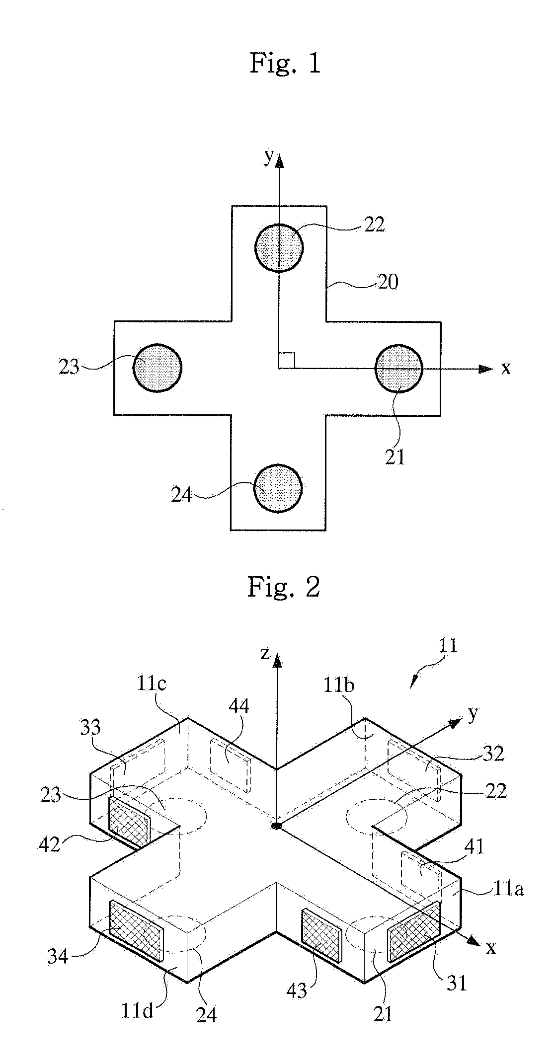
[0049]FIG. 1 is a plan view showing a cross-shaped first force sensor film 20 and a force sensor distribution in a 6-axis force sensor structure using a force sensor according to an embodiment of the present invention. The first force sensor film 20 having distribution of force sensors 21, 22, 23 and 24 is configured to generate electric signals respectively corresponding to uniaxial force and 2-axis moments and output the electric signals to a predetermined calculating means (not shown).

[0050]As shown in FIG. 1, the cross-shaped first force sensor film 20 has the force sensors 21, 22, 23 and 23 distributed in at least four ranges. The force sensors 21, 22, 23 and 24 are respectively arranged on four ends (at distances a and b from the intersecting point of ±x axis and ±y axis) of the cross-shaped the first force sensor film 20 in perpendicular directions (directions of ±x axis and directions of ±y axis perpendicular to ±x axis) and measure uniaxial force and 2-axis moments which wi...

second embodiment

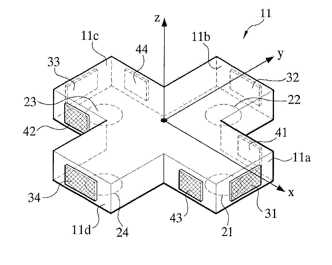
[0063]FIG. 7 shows location of force sensor films on the press member 11 of the cross-shaped bumper 10 of a 6-axis force sensor structure according to a second embodiment of the present invention. Referring to FIG. 7, a force sensor film 90 having force sensors 91, 92, 93 and 94 respectively placed on the top faces of the horizontal beams 11a, 11b, 11c and 11d of the press member 11 is added to the force sensor films 20, 31, 32, 33, 34, 41, 42, 43 and 44 in the first embodiment of the invention shown in FIG. 2. This configuration according to the second embodiment of the invention is for calculating the magnitude of an external force applied to the bumper 10 in consideration of a tensile force when the external force includes the tensile force in addition to a compressive force.

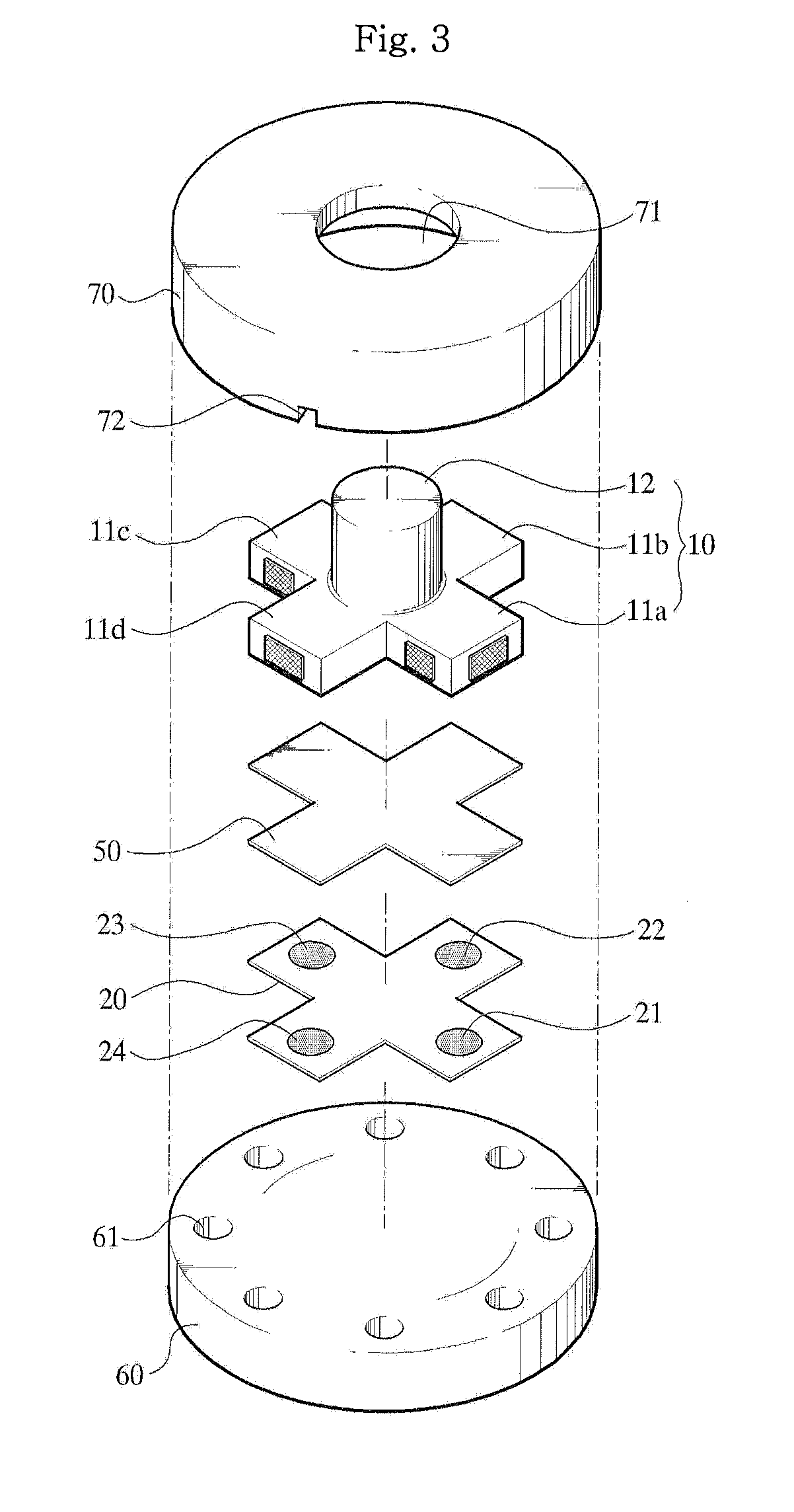
[0064]FIG. 8 is an exploded perspective view of the 6-axis force sensor structure according to the second embodiment of the present invention, viewed downward. The 6-axis force sensor structure according to t...


PUM


Abstract

A 6-axis force sensor includes bumper 10 with bumper axis 12 and press member 11 which has four horizontal beams 11a, 11b, 11c and 11d in a cross shape with end, side and bottom faces. Sensors 31, 32, 33, and 34 on end faces sense force in one direction and sense a moment acting on opposite end faces. Sensors 41, 42, 43, and 44 on side faces sense force in a second direction transverse to the first direction and sense a moment acting on opposite side faces. A film 20 on the bottom faces has four sensors 21, 22, 23, and 24, one on each bottom face, for sensing force in a direction transverse to the first and the second directions and sensing a moment acting on opposite sensors on the film.

Description

BACKGROUND OF THE INVENTION[0001]1. Field of the Invention[0002]The present invention relates to a 6-axis force sensor structure using a force sensor and a method of measuring force and moment therewith. More particularly, the invention relates to a 6-axis force sensor structure which generates electric signals corresponding to forces of 3 axes and the moments of 3 axes using a uniaxial force sensor film having force sensor distribution and a cross-shaped press member and a method of measuring forces and moments of 6 axes using the 6-axis force sensor structure.[0003]2. Background of the Related Art[0004]Most conventional uniaxial / multiaxial load cells use a strain gauge. However, the manufacturing cost of the strain gauge is as high as more than $100 and mass production of the strain gauge is difficult to achieve because the strain gauge is manually manufactured.[0005]Furthermore, the variance of manufactured load cells is considerably large and a resistance variation due to a forc...

Claims


Application Information

Patent Timeline
Patent Type & Authority Applications(United States)
IPC IPC(8): G01D7/00
CPCG01L5/16G01L5/167G01L5/165G01L5/163G01L1/18G01L1/14
Inventor KIM, JONG HOKWON, HYUN JOONKIM, DONG-KI
Owner KOREA RES INST OF STANDARDS & SCI
Why Eureka
Try Eureka