Braking band of a disc for a ventilated-type disc brake

a technology of disc brake and braking band, which is applied in the direction of brake types, braking discs, brake elements, etc., can solve the problems of disc deformation, disc deformation, and deterioration of contact between pads and braking surfaces

Active Publication Date: 2011-05-12
FRENI BREMBO SPA
View PDF7 Cites 21 Cited by
  • Summary
  • Abstract
  • Description
  • Claims
  • Application Information

AI Technical Summary

Benefits of technology

[0011]In accordance with another advantageous embodiment, which is not necessarily implemented in conjunction with the previous one, a braking band has more rows or ranks of pillars, said more ranks of pillars being mutually concentric arranged, and in which the rank arranged in the proximity of the band radially outer edge far from the band rotation axis (X-X) has at least some of the pillars having a substantially triangular transversal section with the base facing towards the disc outer part and sides within the ventilation duct having a concave profile, in which said triangular section extends the concave sides thereof by overlapping the adjacent row or rank in the radial direction.

Problems solved by technology

It is known that the braking action exerted by the pads against the disc braking surfaces generates heat, consequently a temperature increase of the disc, until making the same disc incandescent in the case of a particularly heavy performance.
Due to the high temperature which the disc reaches during the braking action, the disc deforms, and the contact between pads and braking surfaces deteriorates.
Furthermore, the friction material of the pads undergoes a kind of vitrification and pollution by the disc material.
During the disc life, such area is readily prone to the formation of cracks.
While being satisfactory from several point of view, these known solutions do not allow reaching a compromise between mechanical strength which is desired in the braking band central annular area and the conflicting need to maximize, in the same area, the air flow able to eliminate the high localized temperature increase which is caused by the braking action.

Method used


Image

  • Braking band of a disc for a ventilated-type disc brake
  • Braking band of a disc for a ventilated-type disc brake
  • Braking band of a disc for a ventilated-type disc brake

Examples


Embodiment Construction

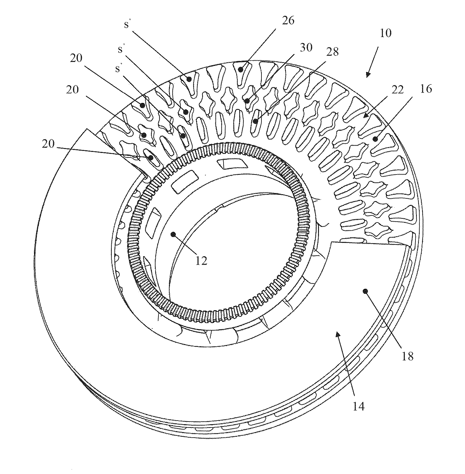
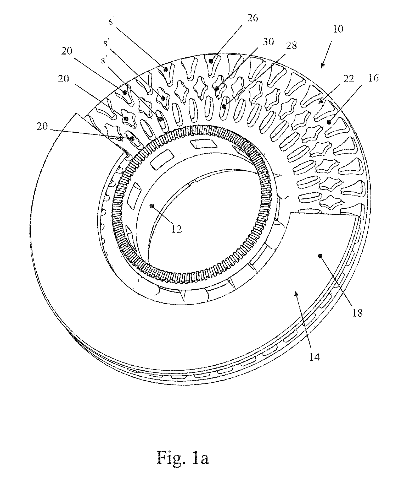
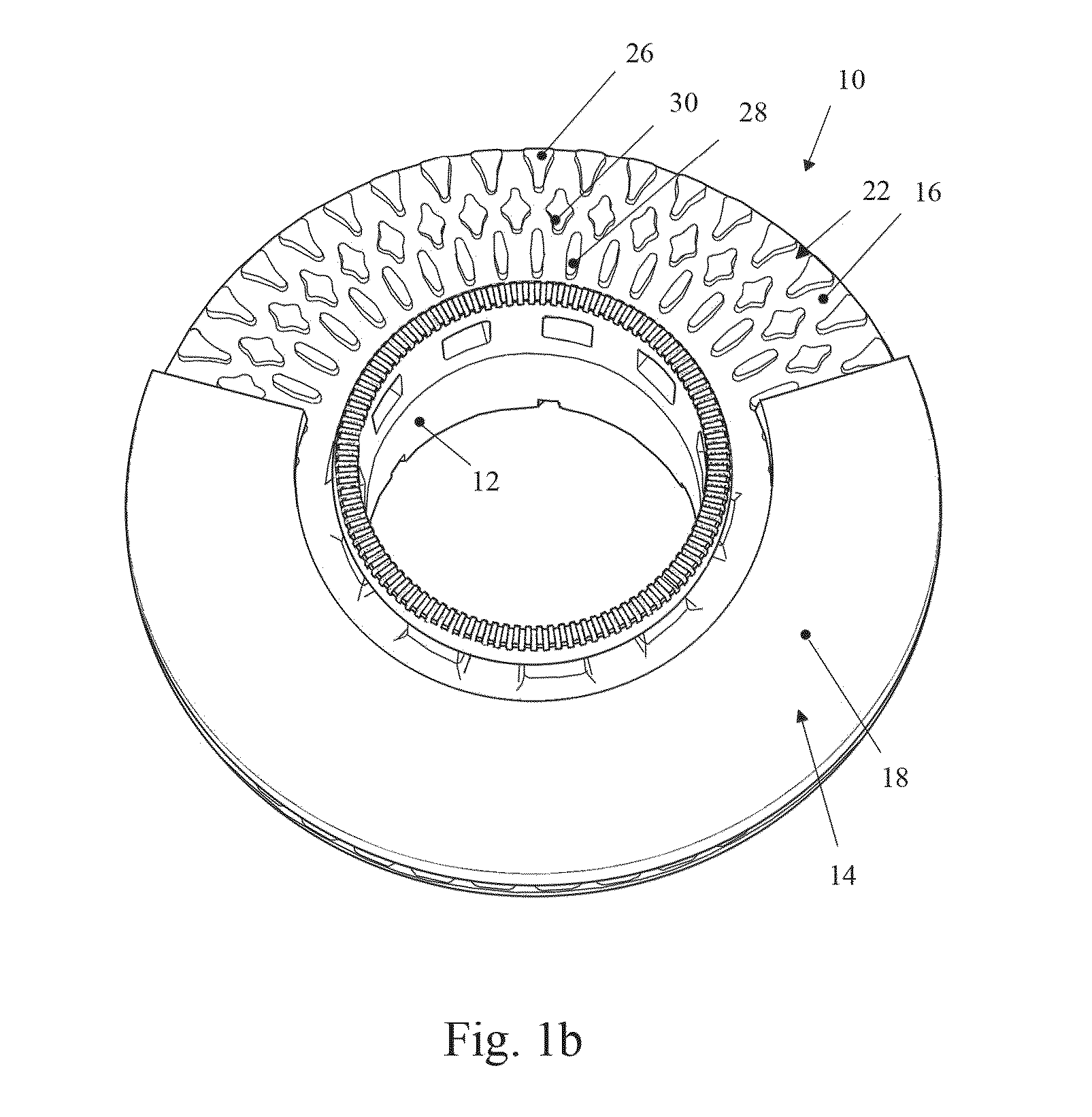
[0023]With reference to the above-mentioned Figures, a disc for a ventilated-type disc brake has been generally indicated with 10. A cap or hub has been indicated with 12, and a braking band has been indicated with 14.

[0024]An axis around which the disc rotates has been indicated with the reference X-X. By direction axial to the disc or braking band is meant a direction parallel to the X-X axis. The radial direction to the disc or braking band, i.e. a direction perpendicular to the axial direction or the X-X axis, has been generally indicated with the reference Z-Z. Finally, by direction T-T tangential or circumferential to the disc is meant a direction tangent to a circumference having its centre on the X-X axis and lying on a plane perpendicular thereto (for example, FIG. 4).

[0025]The braking band 14 extends between an inner diameter D1, near to the disc rotation axis X-X, and an outer diameter D2, far from said disc rotation axis X-X (for example, FIG. 3).

[0026]The braking band c...


PUM


Abstract

A braking band of a disc for a ventilated-type disc brake, uncommonly capable of a high cooling and high resistance to mechanical and thermal stresses, extends between an inner diameter and an outer diameter, said braking band comprises two plates mutually facing and defining an interspace, mutually linked by heat dissipation and connecting means or members; at least some of said connecting means are shaped as small columns projecting from a plate towards the opposite plate in the form of pillars, which are grouped in at least one circumferentially arranged row or rank; at least some of said pillars of said at least one rank have, in a plane substantially parallel to the air flow along the ventilation ducts, a substantially rhombus- or diamond-shaped section with four vertexes joined by four sides, wherein said sides defining said section are concave to form a star shape.

Description

FIELD OF THE INVENTION[0001]It is the object of the present invention a braking band of a disc for a ventilated-type disc brake.BACKGROUND OF THE INVENTION[0002]As it is known, the discs for disc brake comprise a cap or a hub, adapted to associate the disc to a hub of a vehicle, from which an annular portion extends which is called braking band intended to cooperate with pads of a caliper. In the case of the ventilated-type discs, the braking band is obtained by means of two plates respectively facing and mutually connected through connection members, for example in the form of pillars or tabs. The outer surfaces of the two plates define opposite braking surfaces, while the inner surfaces define, in conjunction with the pillars or the tabs, define ventilation ducts for the disc cooling which are passed through by air according to a centrifugal direction during the rotational motion of the same disc.[0003]It is known that the braking action exerted by the pads against the disc brakin...

Claims


Application Information

Patent Timeline
Patent Type & Authority Applications(United States)
IPC IPC(8): F16D65/847F16D65/12
CPCF16D2065/1328F16D65/128
Inventor LEONE, OBERTIGIANLUIGI, MARONATI
Owner FRENI BREMBO SPA
Why Eureka
Try Eureka