

Parabolic rifle rest
- Summary
- Abstract
- Description
- Claims
- Application Information
AI Technical Summary
Benefits of technology
Problems solved by technology
Method used
Image

Examples
Embodiment Construction
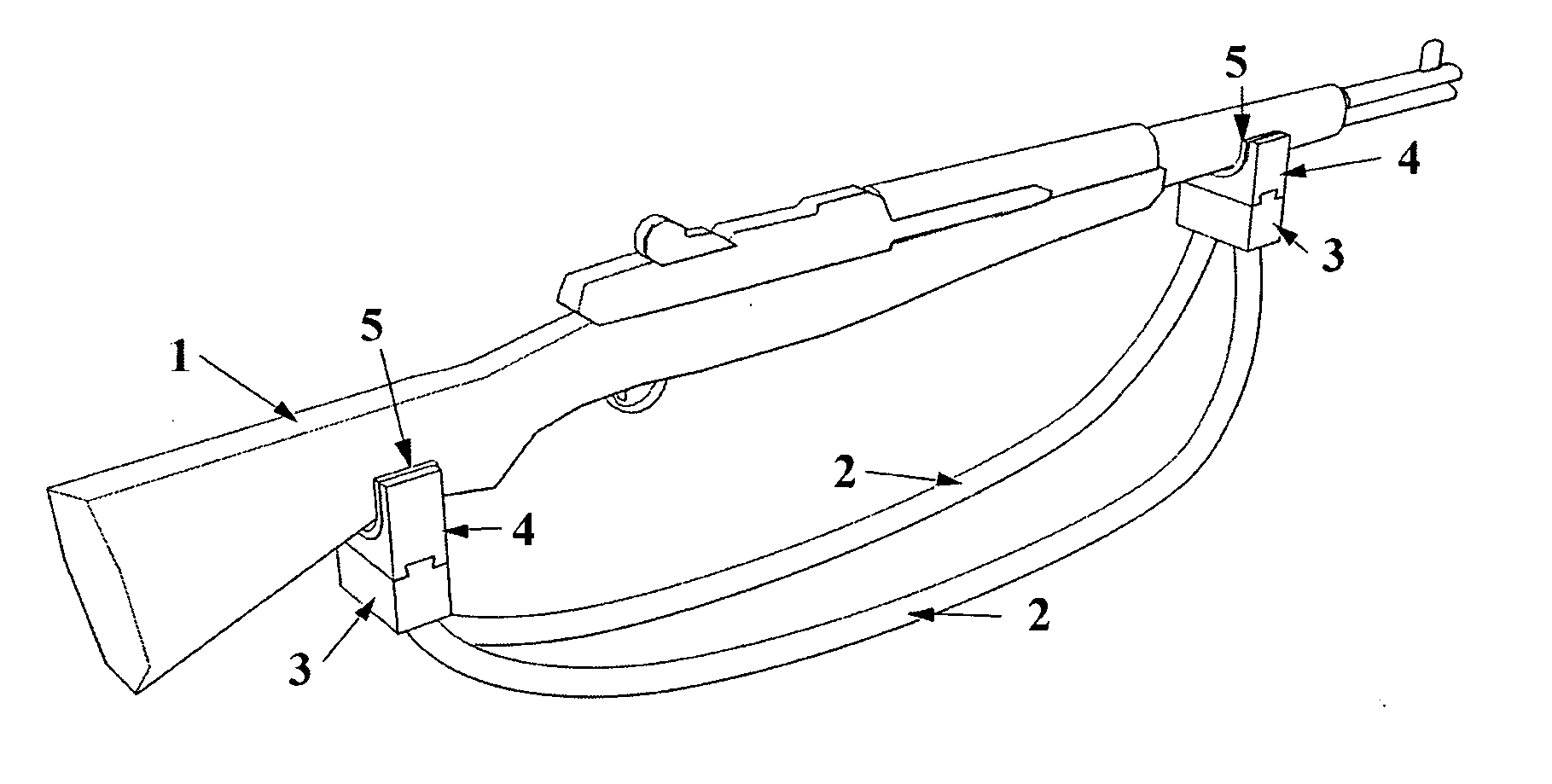
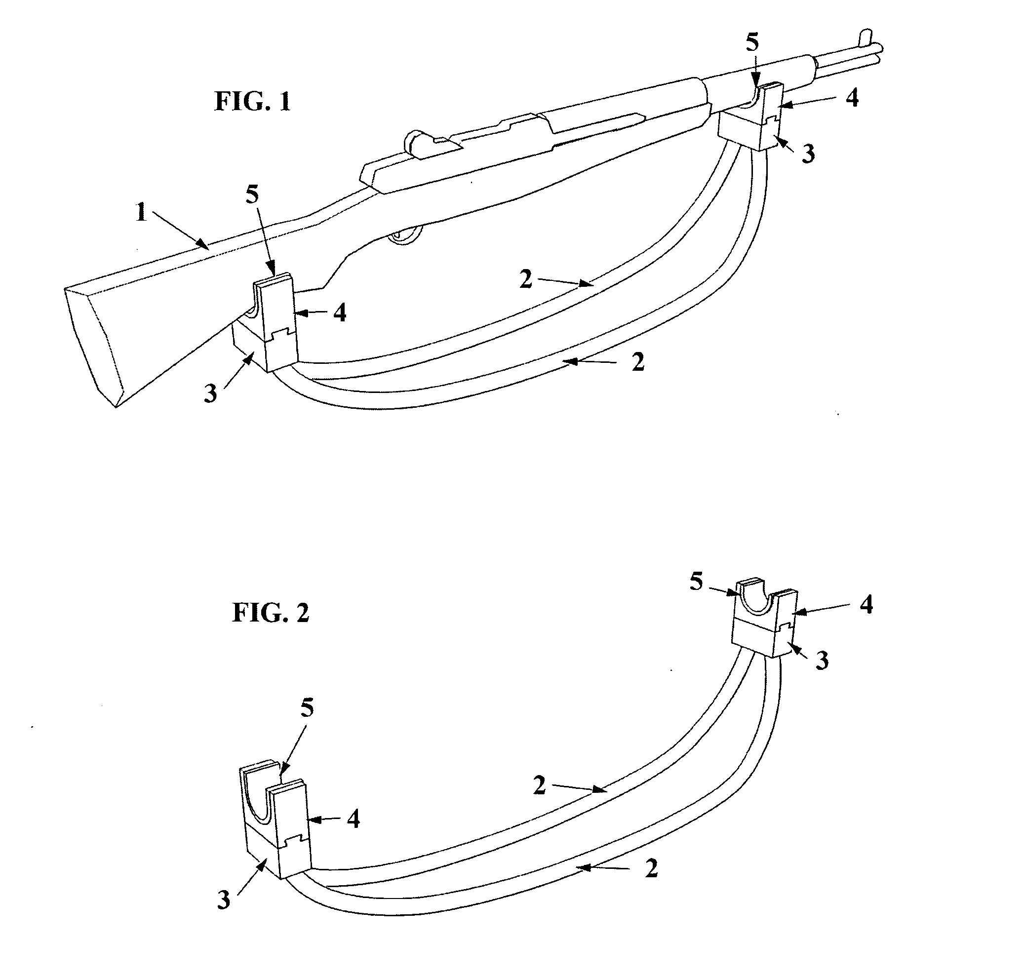
The disclosed Invention is that of a rifle rest, comprised of a rocking base formed by first and second generally arc shaped members 2, each having a generally convex bottom surface adapted for rocking motion, joined together in a generally parallel spaced relationship by cross-members or blocks 3 at either end of the generally arc-shaped members 2, and including U-shaped grips or supports 4 attached to these cross-members or blocks, upon which U-shaped grips or supports 4 the rifle 1 rests, in a generally horizontal position.
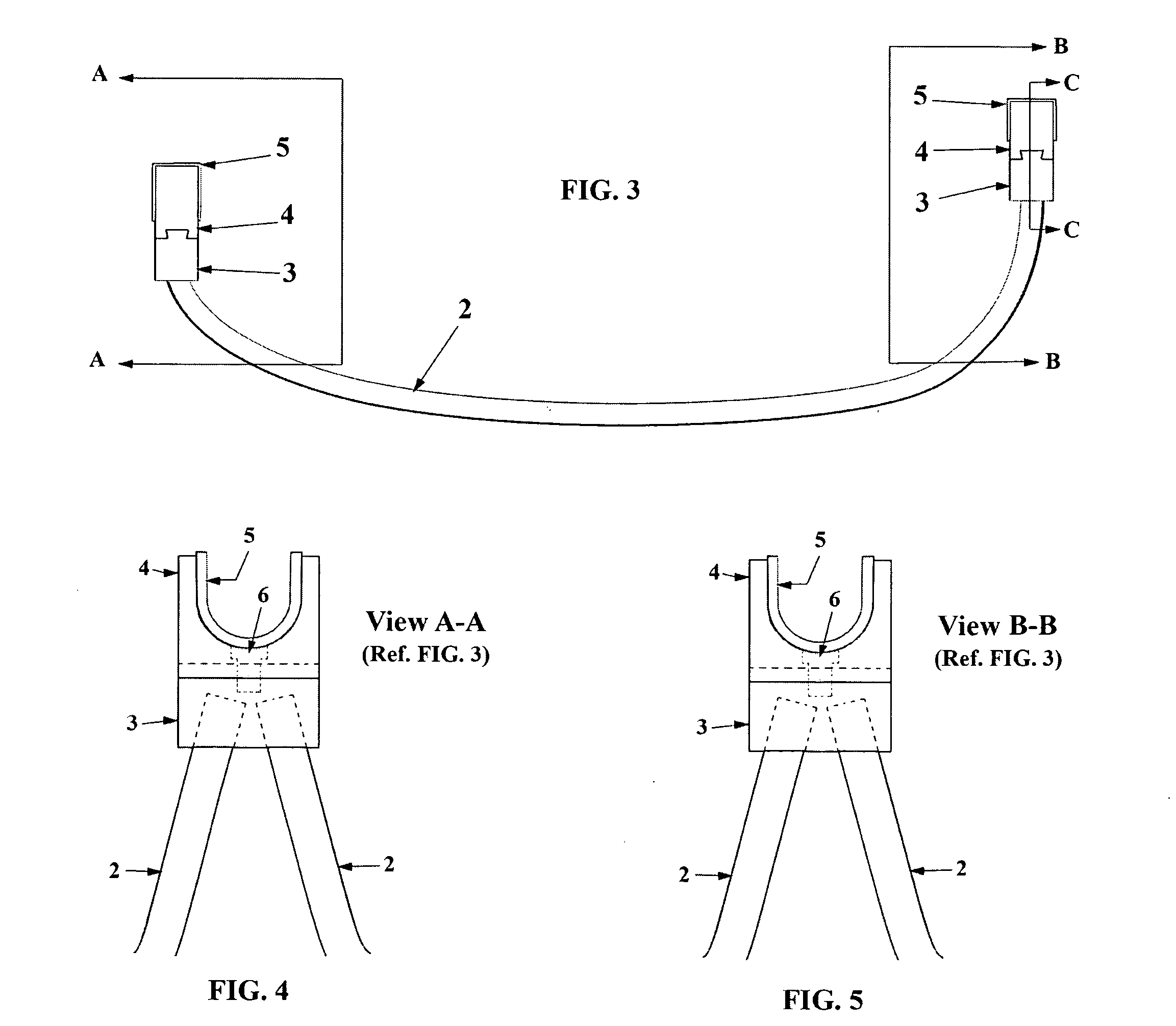
The generally arc-shaped members 2, with their general curvature shown in the side view FIG. 3, are inserted into bores or holes in the cross-members or blocks 3 as shown in FIG. 7, in a generally parallel spaced relationship, such that the Invention forms an arc-shaped rocking base.
The U-shaped grips or supports 4, including a protective layer such as soft rubber or wool felt 5 which protects the rifle 1 from scuffing, are slideably attached to cross-members o...
PUM
 Abstract
Description
Claims
Application Information