Locking arrangement

a technology of locking arrangement and locking mechanism, which is applied in the direction of mechanical control devices, keyhole guards, restricting/preventing/returning movement of parts, etc., can solve the problems of wasting even more time, wasting more time, and wasting more tim

Inactive Publication Date: 2011-05-19
DAVID STUCKEY INVESTMENTS
View PDF29 Cites 10 Cited by
  • Summary
  • Abstract
  • Description
  • Claims
  • Application Information

AI Technical Summary

Benefits of technology

[0011]The locking bar preferably includes a first shoulder and a second shoulder against which an override means of the secondary locking mechanism is independently urged to reversibly move the locking bar between the extended latching position and the retracted release position. Preferably further, the locking bar includes a cut-out region into which the override means is receivable.
[0012]The locking bar more preferably further includes a first catch means interaction zone and a second catch means interaction zone, wherein, when the locking bar is in the extended latching position, the biased catch means interacts with the first catch means interaction zone to releasably retain the locking bar in the extended latching position, and when the locking bar is in the retracted release position, the biased catch means interacts with the second catch means interaction zone to releasably retain the locking bar in the retracted release position.
[0013]In one preferred embodiment of the present invention, the handle assembly comprises a handle, a handle shaft, a slotted disc and a locking cam, wherein the handle, the slotted disc an

Problems solved by technology

The presence of such lockable doors brings with it a problem where each door requires its own key for moving its locking mechanism between its locked and unlocked conditions.
For the driver to walk around the truck, unlocking and then relocking each door, comes at a time cost penalty, which is exacerbated when the doors do not have common locks and each requires a different key.
In addition, before the driver either leaves his vehi

Method used


Image

  • Locking arrangement
  • Locking arrangement
  • Locking arrangement

Examples


Embodiment Construction

[0025]Referring to all the drawings wherein like reference numerals designate like or corresponding parts throughout the several views, the following description refers to the specific, illustrated embodiments of the present invention and is in no way intended to limit the scope of the present invention to the specific, illustrated embodiments.

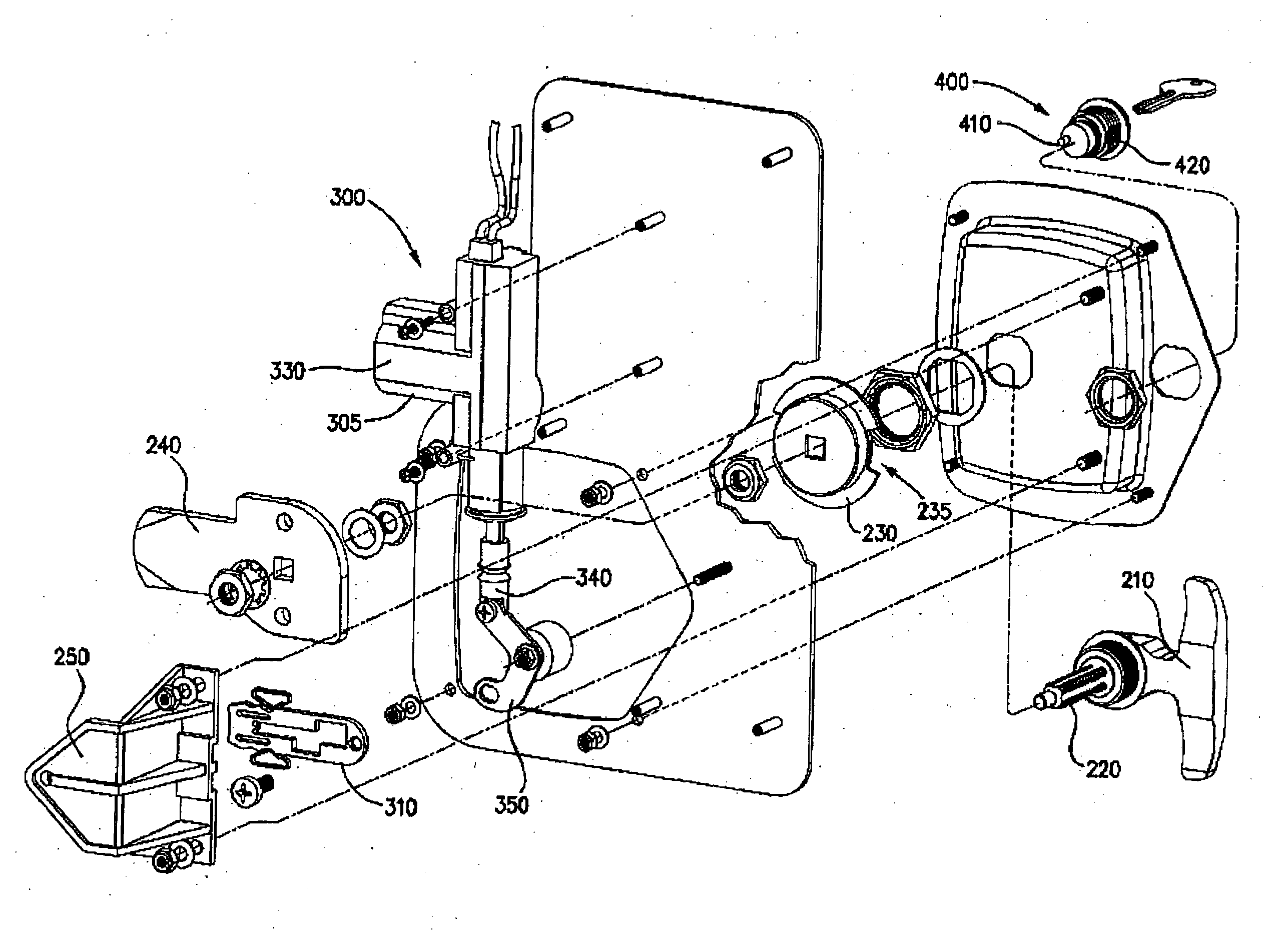
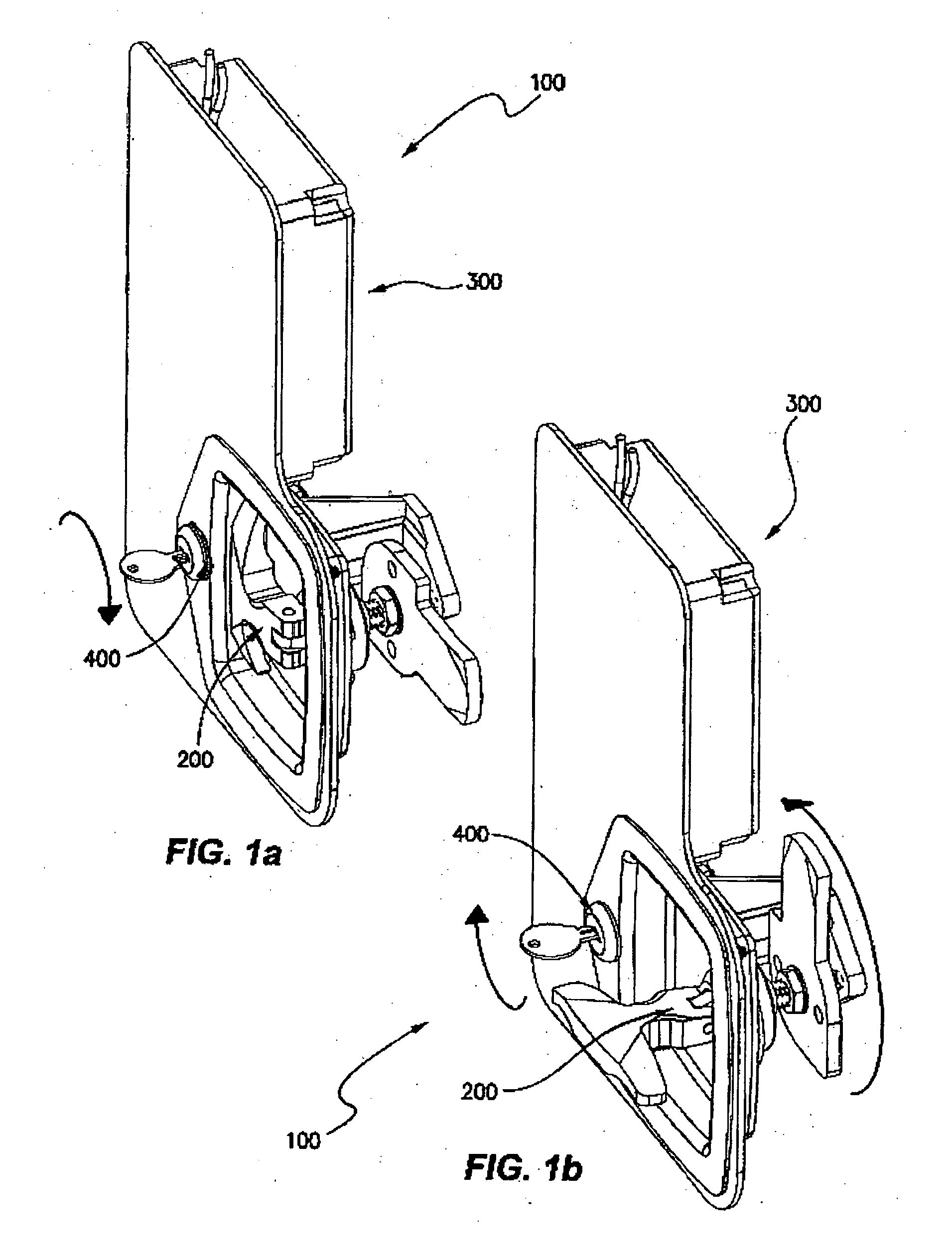
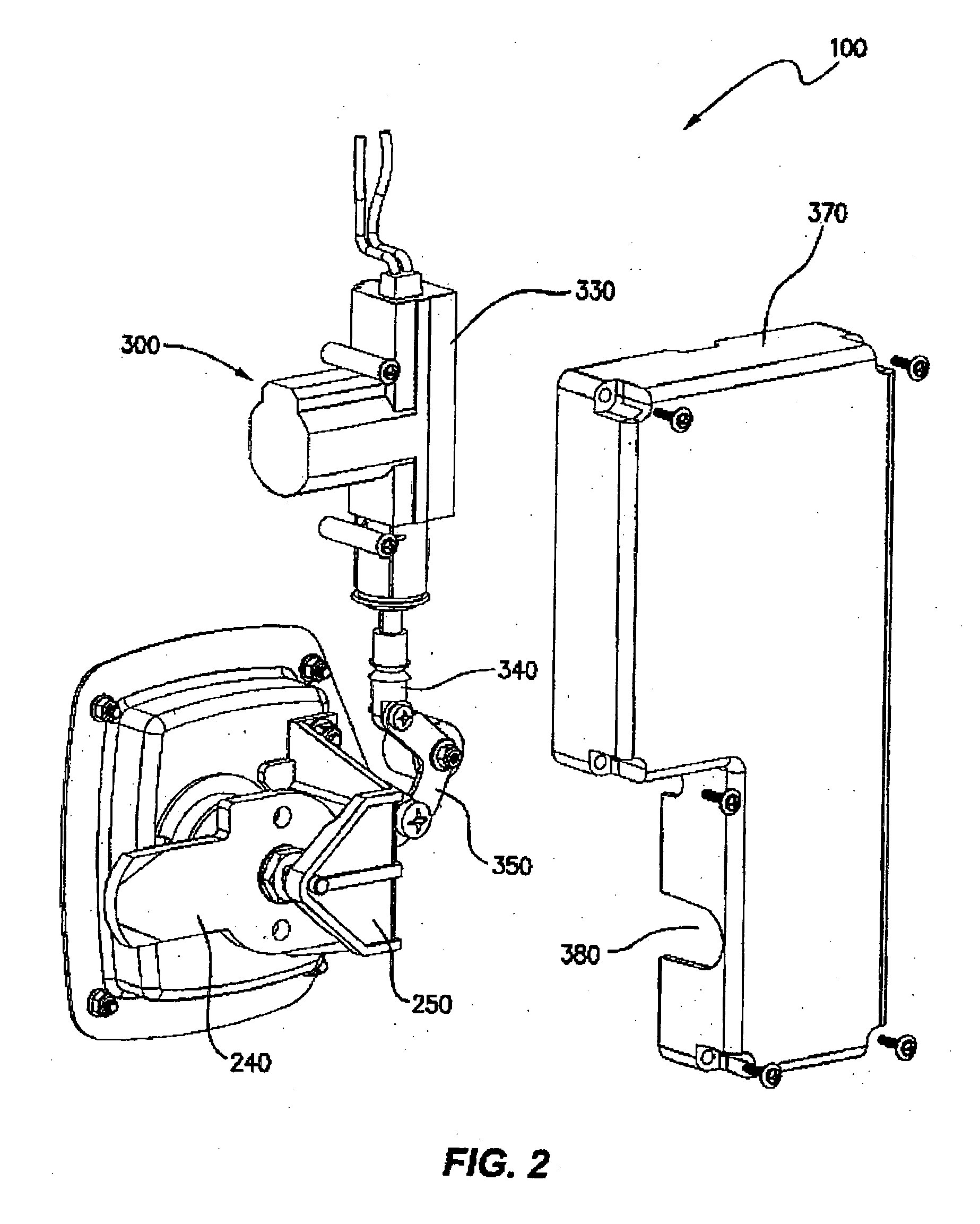
[0026]The illustrated embodiments of a locking arrangement 100 of the present invention comprise a lockable T-handle assembly 200 having a primary 300 and a secondary 400 locking mechanism. Each of the primary 300 and secondary 400 lacking mechanisms may be used independently to move a locking bar 310 between an extended latching position and a retracted release position.

[0027]Referring to FIG. 4, the T-handle assembly 200 includes a handle 210 attached to a handle shaft 220 such that rotation of the handle 210 results in rotation of the handle shaft 220. Mounted on or fixed to the shaft 220 is a slotted disc 230 and locking cam 240, which are...


PUM


Abstract

A locking arrangement comprising: (a) a handle assembly; (b) a primary locking mechanism comprising: (i) a locking bar movable between an extended latching position and a retracted release position, whereby when the locking bar is in the retracted release position the handle assembly is movable between a locked condition and an unlocked condition; and (ii) an actuator means which acts upon the locking bar to move the locking bar between the extended latching position and the retracted release position; (c) a secondary locking mechanism which acts independently upon the locking bar to move the locking bar between the extended latching position and the retracted release position; and (d) at least one biased catch means to releasably retain the locking bar in either the extended latching position or the retracted release position.

Description

FIELD OF THE INVENTION[0001]The present invention relates to a locking arrangement, preferably a locking arrangement for use with a lockable access point such as doors, storage containers, compartments, covers / hatches, transport boxes and bags and the like on vehicles including motor vehicles or cycles. The invention particularly relates to a locking arrangement whereby a primary locking mechanism may be overridden by a secondary locking mechanism.BACKGROUND OF THE INVENTION[0002]Transport / delivery trucks are often configured for security reasons with enclosed rear van areas, whereby access to the goods located therein is via one or more lockable doors. Similarly, recreational vehicles including mobile homes often contain hollow compartments that act as storage areas, where access to the inside of the compartment is via at least one door or hatch located on the outside of the vehicle's body.[0003]A tradesperson's vehicle in the form of a motor vehicle utility often has one or more t...

Claims


Application Information

Patent Timeline
IPC IPC(8): E05B47/02E05C1/10E05B63/14
CPCE05B47/0603E05B47/0673E05B77/46E05B81/16E05C3/042E05B81/90E05B81/08E05B83/12Y10T70/625Y10T70/5761Y10T292/57Y10T292/1028Y10T70/65
Inventor STUCKEY, DAVID MARTIN
Owner DAVID STUCKEY INVESTMENTS
Why Eureka
Try Eureka