Device, Method, and Apparatus for Lifting a Railway Rail

a technology for lifting and rails, applied in railway tracks, railway track construction, ways, etc., can solve the problems of unsuitable high-speed trains, most extension, and uneven rails, and achieve the effect of stabilising the rail, lifting and lowering process, and preventing lateral movement of the rail

Active Publication Date: 2011-05-19
PANDROL VORTOK LTD
View PDF10 Cites 0 Cited by
  • Summary
  • Abstract
  • Description
  • Claims
  • Application Information

AI Technical Summary

Benefits of technology

According to an embodiment of a first aspect of the present invention, there is provided a railway-rail-lifting device for lifting a railway rail, the device comprising: an arm; and a roller rotatably mounted to the arm; the arm being operable to be rotated to bring the roller to bear on the rail such that the roller exerts a lifting force thereon; characterised by securing means operable to releasably secure the device to a rail fastening assembly. Such a device advantageously renders a separate jack and roller unnecessary. Furthermore, by eliminating the need for a separate jack and roller, the above-mentioned problems and safety hazards associated with coordinating the use of such jacks and rollers are also eliminated. The use of the existing rail fastening assembly to locate the device is advantageous, as it avoids the need to provide other means to which the device may be secured.
It is advantageous to use first and second devices on opposite sides of the rail in order to stabilise the rail on lifting, and prevent lateral movement of the rail. In this way, it may be possible to ensure that the rail is positioned centrally with respect to the rail fastening assembly throughout extension of the rail, in order to facilitate reattachment of the rail to the rail fastening assembly after the tensioning is complete. Such lateral movement may be movement towards or away from a center of curvature in the case of a curved rail section.

Problems solved by technology

Unless well maintained, jointed track provides a characteristic bumpy, noisy and uncomfortable ride due to the presence of the expansion joints, and is unsuitable for high speed trains because it is too weak.
As welded track has very few expansion joints, it could become distorted in hot weather and cause a derailment.
In practice, however, friction between the rail length and the sleeper fittings causes most of the extension to occur close to the tensing point (the initially free end).
The consequence of this is to concentrate the load nearest the gap and thus overstress the rail at the weld.
This can lead to rail breaks.
At the other end, nearest to the anchor, the rail can be unstressed and may buckle in hot weather due to thermal expansion.
There are a number of problems with the above-mentioned existing practice.
The use of separate jacks, rollers and side rollers is inconvenient, and as a result the rail stressing process is time-consuming and expensive.
Firstly, the use of separate pieces of equipment may necessitate the involvement of several people in order to coordinate the rail-lifting step, the placement of rollers and side rollers, and the rail-lowering step.
The lifting of a heavy rail and the placing of rollers thereunder is a hazardous operation for hands that may become trapped.
Although the existing rollers relieve significant friction which would otherwise oppose extension of the rail, they still exert some drag to the free movement of the rail.
This underside face is normally close to the ground when the rail is in its working position, and is therefore subject to corrosion and may pick up debris.
Rolling on this surface is not ideal.
Such a tool requires simple lifting of the rail by hand, and as a result only very small lengths may be lifted for any reasonable length of time.
As above-mentioned, it is inconvenient to have to use separate rollers and side rollers.
It is considered disadvantageous that such an off track machine be required.
Such off track machinery is commonly expensive, requires regular maintenance, may require a large electrical power source, and can be difficult to transport and position securely for use.

Method used


Image

  • Device, Method, and Apparatus for Lifting a Railway Rail
  • Device, Method, and Apparatus for Lifting a Railway Rail
  • Device, Method, and Apparatus for Lifting a Railway Rail

Examples


first embodiment

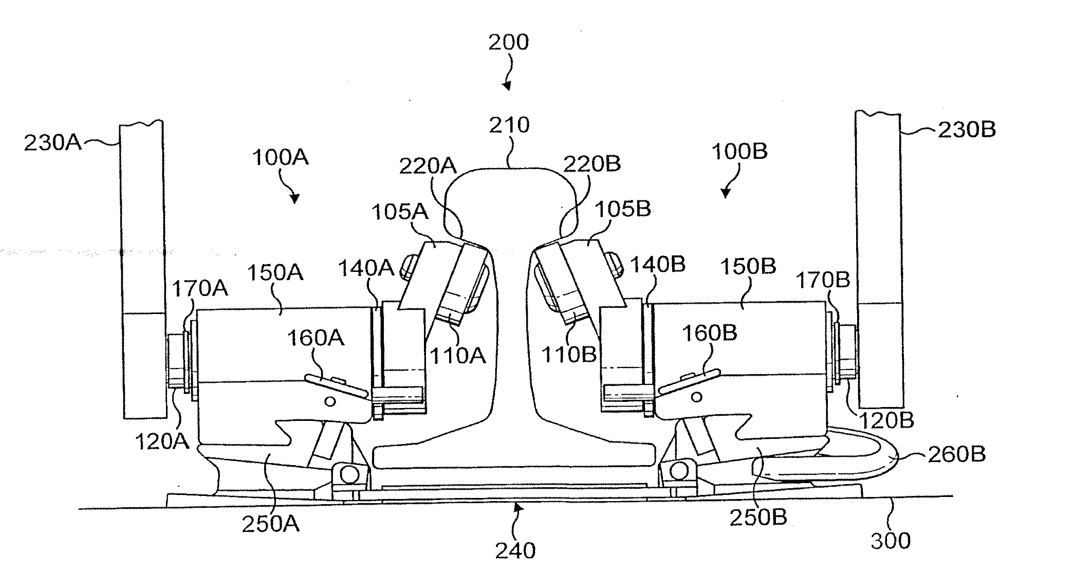
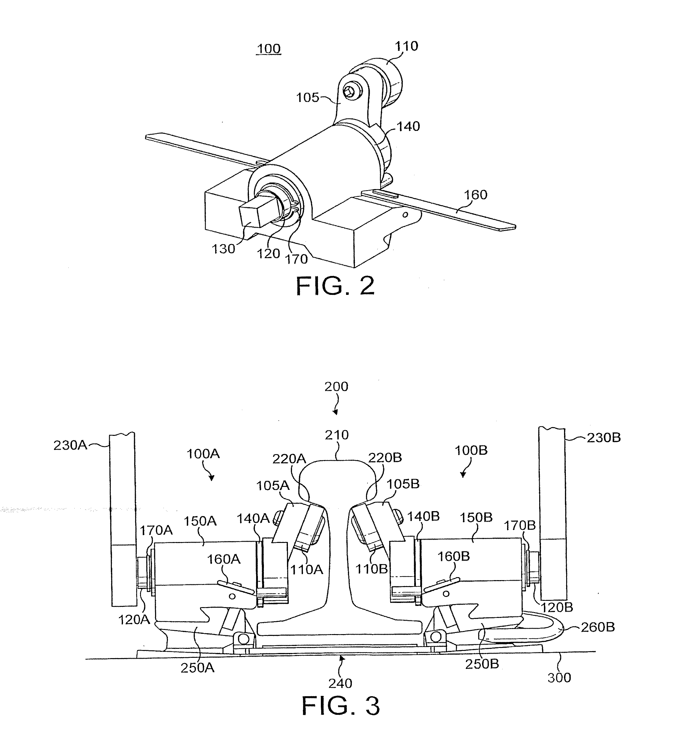
FIG. 2 of the accompanying drawings shows a device 100 according to the present invention. Device 100 comprises a lift arm 105, a roller comprising a bearing 110, a shaft 120, a spacer 140, a mount assembly 150, two locking handles 160, and a circlip 170.

The bearing 110 is rotatably mounted at a predetermined angle to one end of the arm 105. The arm 105 is coupled at its other end to one end of the shaft 120. The shaft is substantially housed within the mount assembly 150, preferably in at least one axial bearing (not shown), and / or with at least one thrust bearing (not shown).

Spacer 140 is located between the arm 105 and the mount assembly 150, so as to maintain a minimum distance between the arm 105 and the mount assembly. It is envisaged that spacer 140 is an optional component of device 100. Circlip 170 is located on a portion of the shaft 120 protruding out of the mount assembly 150 away from the arm 105. The shaft 120 is free to move axially within the mount assembly 150, but ...

third embodiment

FIG. 5 of the accompanying drawings shows a device 1100 according to the present invention. Device 1100 comprises a lift arm 1105, a roller comprising a bearing 1110, a bearing shaft 1300, a shaft 1120, a handle stub 1310, two bearings 1122 and 1124, a circlip 1170, a washer 1172, a mount assembly 1150, a carrying strap 1800, and securing means 2000.

Securing means 2000 comprises two locking fingers 2010 and 2020, two finger pins 2030 and 2040 (not shown), two finger spring pins 2032 and 2042 (not shown), a finger spring 2050, two bell cranks 2060 and 2070 (not shown), two washers 2080 and 2090 (not shown), two finger circlips 2100 and 2110 (not shown), push button 2120, and roll pin 2130.

The bearing 1110 is rotatably mounted onto bearing shaft 1300, which is itself mounted to one end of the arm 1105 such that bearing 1110 is mounted at a predetermined angle relative to the arm 1105. The arm 1105 is coupled at its other end to one end of the shaft 1120. The shaft is supported within ...

fourth embodiment

FIGS. 9 to 11 of the accompanying drawings show three perspective views of apparatus 3000 according to the present invention in different stages of use. Apparatus 3000 comprises two devices 1100A and 1100B, each substantially identical to the aforementioned device 1100.

In addition to apparatus 3000. FIGS. 9 to 11 show a rail 3210, and a rail fastening assembly 3240 which rests upon a sleeper 3300.

The reference numerals used in respect of device 1100, also apply to devices 1100A and 1100B, except with additional respective suffixes A and B. Accordingly, unnecessary duplicate description of those parts is omitted.

Turning firstly to FIG. 9, device 1100A is positioned in its working disposition on one rail fastener housing 3250A of the rail fastening assembly 3240. Similarly, device 1100B is positioned in its working disposition on the other rail fastener housing 3250B (not shown) of the rail fastening assembly 3240. A rail fastener 3260A remains within rail fastener housing 3250A in a ...


PUM


Abstract

A railway-rail-lifting device for lifting a railway rail comprises an arm and a roller rotatably mounted to the arm. The arm is operable to be rotated to bring the roller to bear on the rail such that the roller exerts a lifting force thereon. Securing means are operable to releasably secure the device to a rail fastening assembly.

Description

FIELD OF THE DISCLOSUREThe present invention relates to a device, method and apparatus for lifting a railway rail.BACKGROUNDThere are different ways of joining railway rails together to form tracks. One such way is to bolt rails together to form jointed track. In this form of track, lengths of rail, usually around 20 meters in length, are laid and fixed into position. In the UK the track lengths are traditionally fixed to sleepers, and in the USA they are traditionally fixed with crossties, or simply ties. Once laid, the track lengths are then joined together with steel plates, known as fishplates or joint bars.Small gaps are deliberately left between the rails, which are known as expansion joints, to allow for thermal expansion of the rails in hot weather. Additionally, the holes through which the fishplate bolts pass are normally oval to allow for expansion.Unless well maintained, jointed track provides a characteristic bumpy, noisy and uncomfortable ride due to the presence of th...

Claims


Application Information

Patent Timeline
Patent Type & Authority Applications(United States)
IPC IPC(8): E01B29/04E01B29/22
CPCE01B29/22E01B29/04
Inventor BOINTON, RICHARDSVENDSEN, JAN A.
Owner PANDROL VORTOK LTD
Why Eureka
Try Eureka