Incremental hybrid welding systems and methods

a hybrid welding and hybrid welding technology, applied in the field of hybrid welding systems, can solve the problems of inefficient activation of the engine-generator to meet such small load demands, and achieve the effect of reducing the number of welding operations

Active Publication Date: 2011-05-19
ILLINOIS TOOL WORKS INC
View PDF37 Cites 56 Cited by
  • Summary
  • Abstract
  • Description
  • Claims
  • Application Information

AI Technical Summary

Benefits of technology

The patent describes a welding system that includes an engine, a battery, and a charger. The system can produce power either from the engine or from the battery, depending on the commanded output. The system also includes control circuitry to detect the commanded output and meet it by controlling the access to power from the battery or the engine-generator. The technical effect of this patent is to provide a flexible and efficient welding system that can adjust its power output based on the commanded output, allowing for better control and performance during welding operations.

Problems solved by technology

The patent text discusses the need for portable welding devices that can be easily transported to remote locations and operated as standalone units. These devices often use batteries as an alternate power source, but the engine-generator unit is often inefficient in meeting small load demands. The technical problem addressed in this patent is the need for hybrid welding systems that can overcome these drawbacks.

Method used


Image

  • Incremental hybrid welding systems and methods
  • Incremental hybrid welding systems and methods
  • Incremental hybrid welding systems and methods

Examples


Embodiment Construction

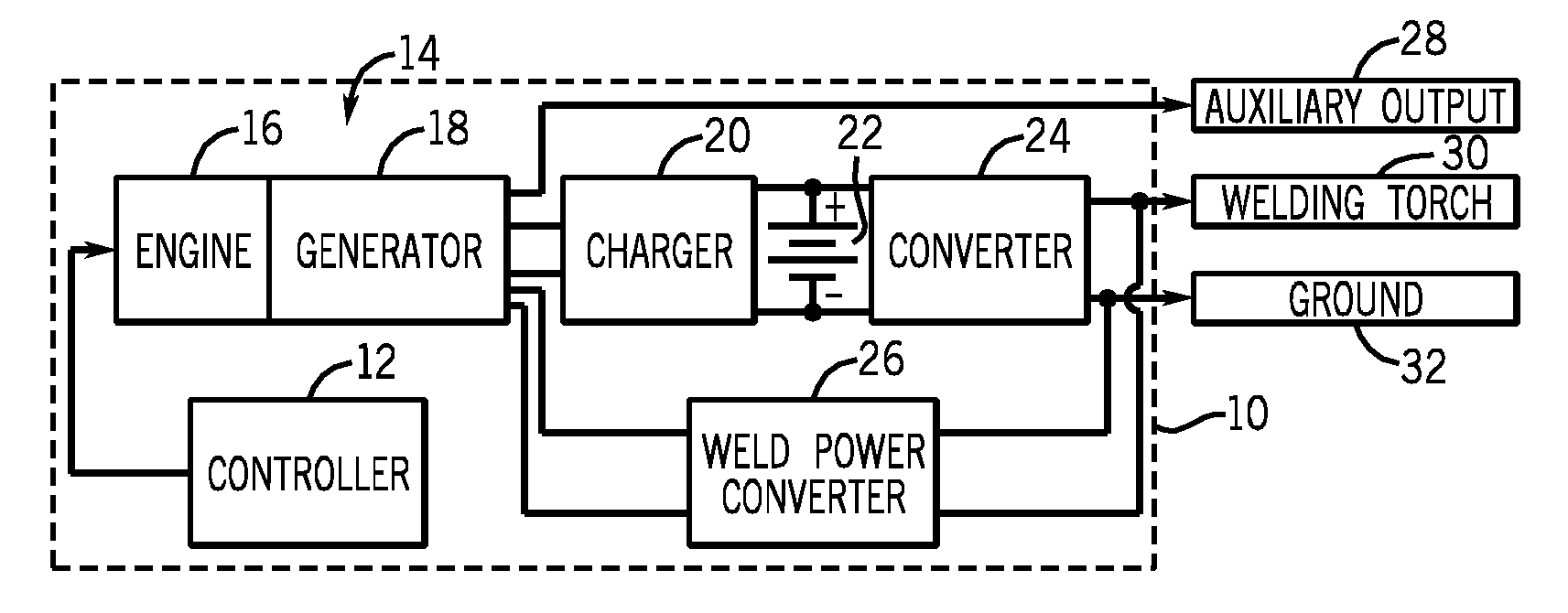
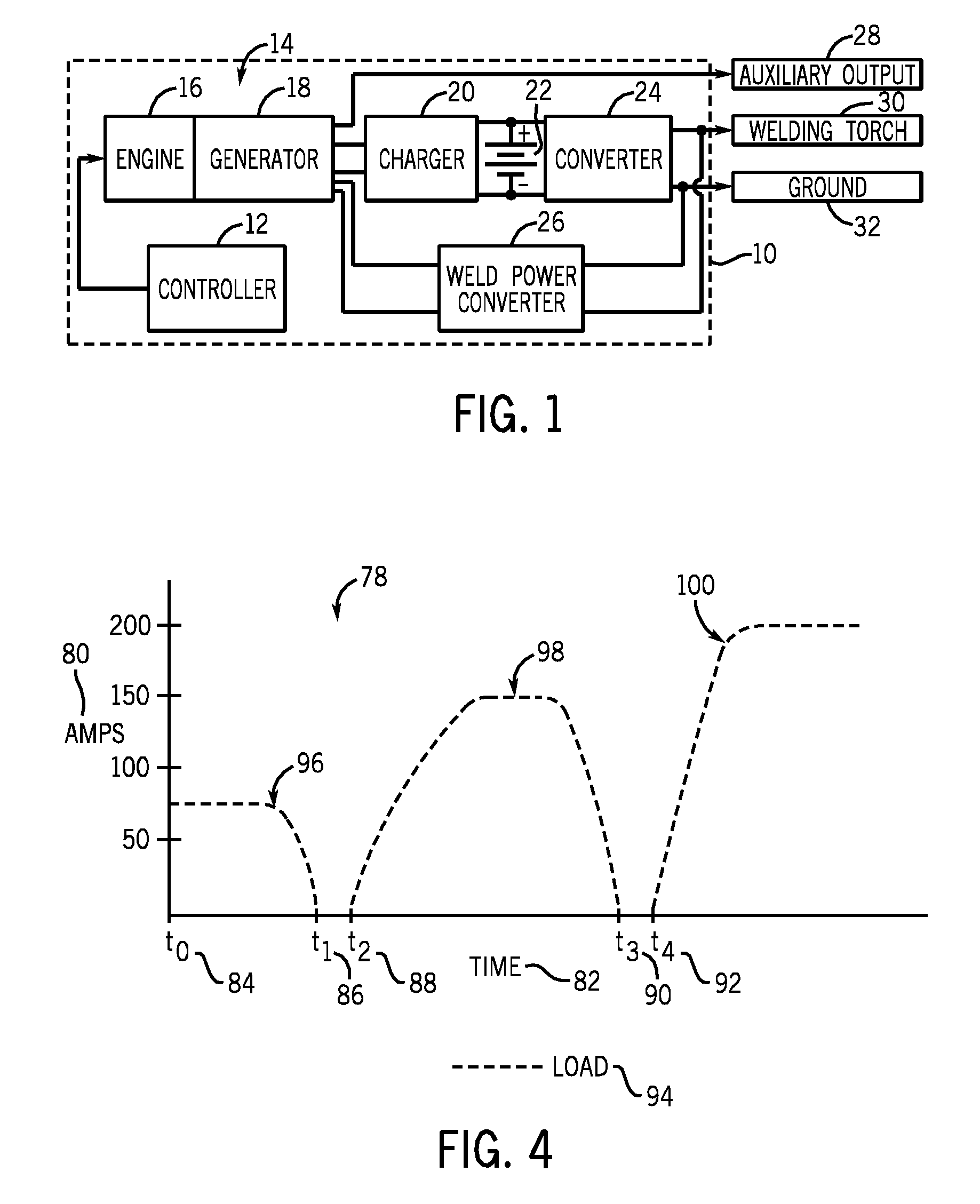
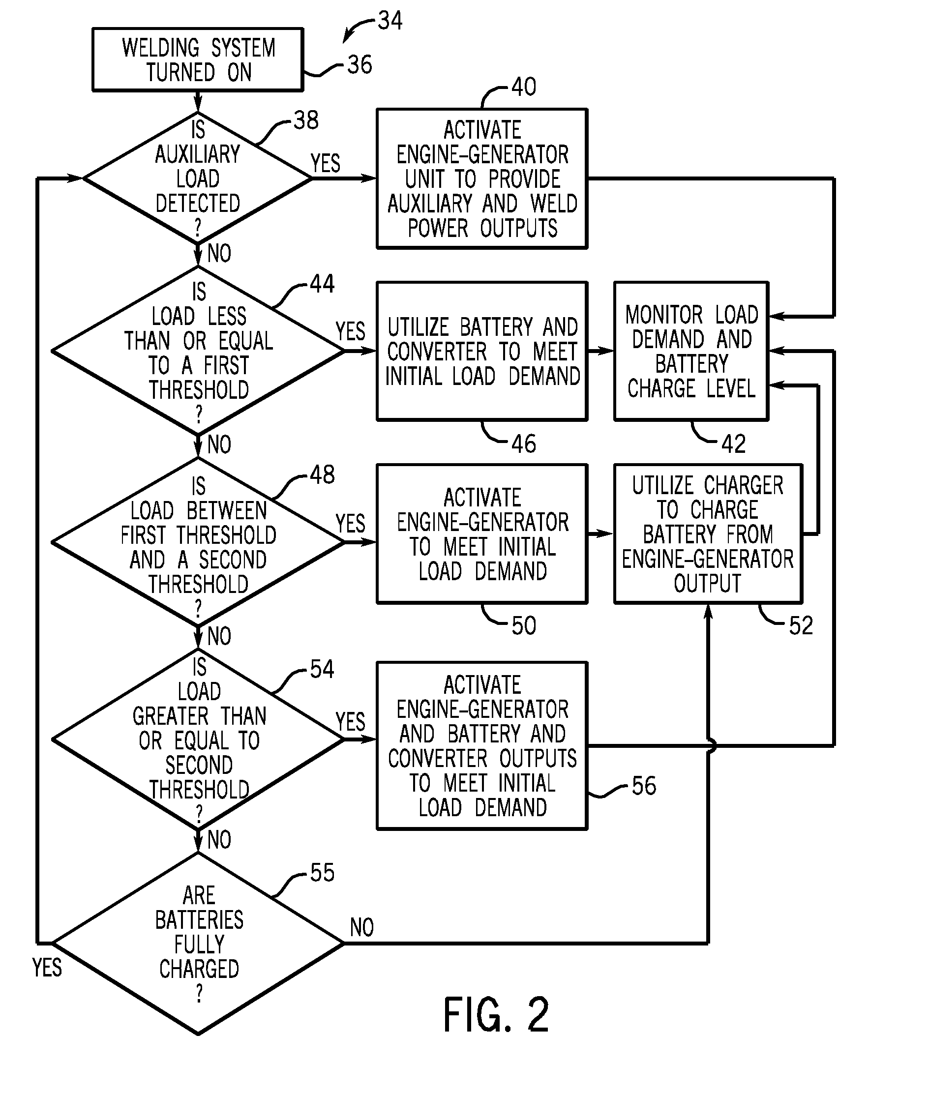
[0013]As described in detail below, embodiments of an incremental hybrid welding system and methods of controlling such a system are provided. Embodiments of the hybrid welding system may be adapted to provide output power to meet small load requirements (e.g., less than approximately 150 amps) commanded by an operator without activation of an engine-generator unit disposed therein. For example, the hybrid welding system may include an energy storage device (e.g., a battery, a capacitor, etc.) coupled to an associated converter and capable of meeting small commanded output requirements. Indeed, although embodiments of the present invention are described below in the context of a battery based system, additional embodiments may include any of a variety of suitable energy storage devices, such as capacitors, fuel cells, etc. Furthermore, embodiments of the disclosed hybrid welding systems may include engines with ratings below approximately 22 horsepower (hp), approximately 23 hp, app...


PUM

PropertyMeasurementUnit
Poweraaaaaaaaaa
Poweraaaaaaaaaa
Poweraaaaaaaaaa

Abstract

Embodiments of a welding power supply include an engine adapted to drive a generator to produce a first power and a energy storage device adapted to discharge energy to produce a second power. The welding power supply also includes control circuitry adapted to detect a commanded output. The control circuitry is adapted to meet the commanded output by controlling access to power from the energy storage device to produce the second power when the commanded output is below a first predetermined load level. The control circuitry is further adapted to meet the commanded output by controlling access to power from the engine and the energy storage device to produce the first power and the second power when the commanded output is above a second predetermined load level.

Description


Claims


Application Information

Patent Timeline
Owner ILLINOIS TOOL WORKS INC
Why Eureka
Try Eureka