Modular data over power converter for welding power supply

a power supply and module technology, applied in the field of welding systems, can solve the problems that the wirefeeder may not work with the conventional power supply, and achieve the effect of improving the service life of the wirefeeder

Inactive Publication Date: 2012-04-26
ILLINOIS TOOL WORKS INC
View PDF8 Cites 54 Cited by
  • Summary
  • Abstract
  • Description
  • Claims
  • Application Information

AI Technical Summary

Benefits of technology

[0005]There present invention provides a novel welding system designed to respond to such needs. The system may be used in a wide range of settings, but is particularly well-suited to applications in which a welding power supply and a wirefeeder are used at some considerable distance from one another. The invention is well-suited to applications where a power supply is incapable of combining data with welding power, but a wirefeeder is capable of separating data from welding power signals. The invention therefore provides back compatibility for many thousands of power supplies that would not otherwise be capable of operating with such wirefeeders. The invention is particularly attractive for operations that may have a suite of wirefeeders that may now operate with both more sophisticated power supplies (capable of combining data with welding power) and more conventional welding power supplies.

Problems solved by technology

A current problem in the field, however, results from the incompatibility of many power supplies with wirefeeders designed for use with power supplies that are capable of transmitting data and welding power over the same cable.
That is, while wirefeeders and power supplies work well together when both equipped to modulate and de-modulate data over welding power, these improved wirefeeders may not function with conventional power supplies that are designed to transmit data over a separate control cable.

Method used


Image

  • Modular data over power converter for welding power supply
  • Modular data over power converter for welding power supply
  • Modular data over power converter for welding power supply

Examples


Embodiment Construction

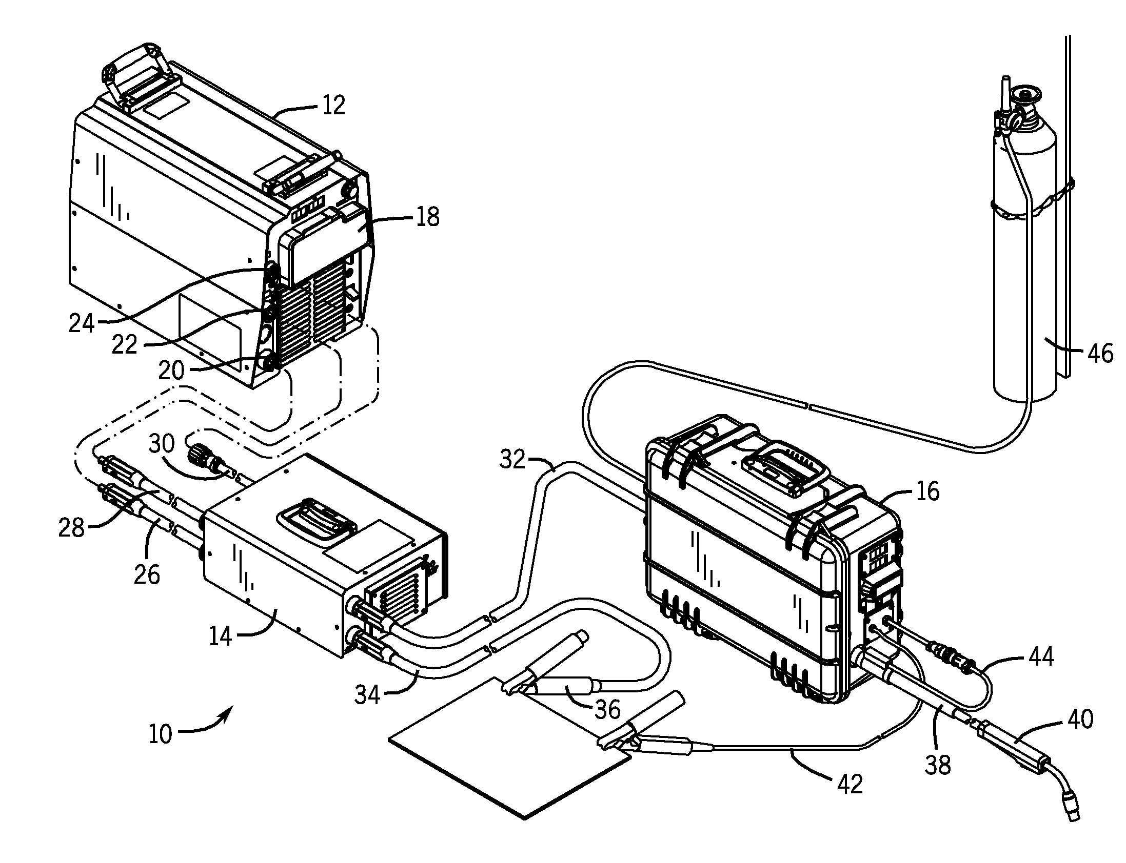
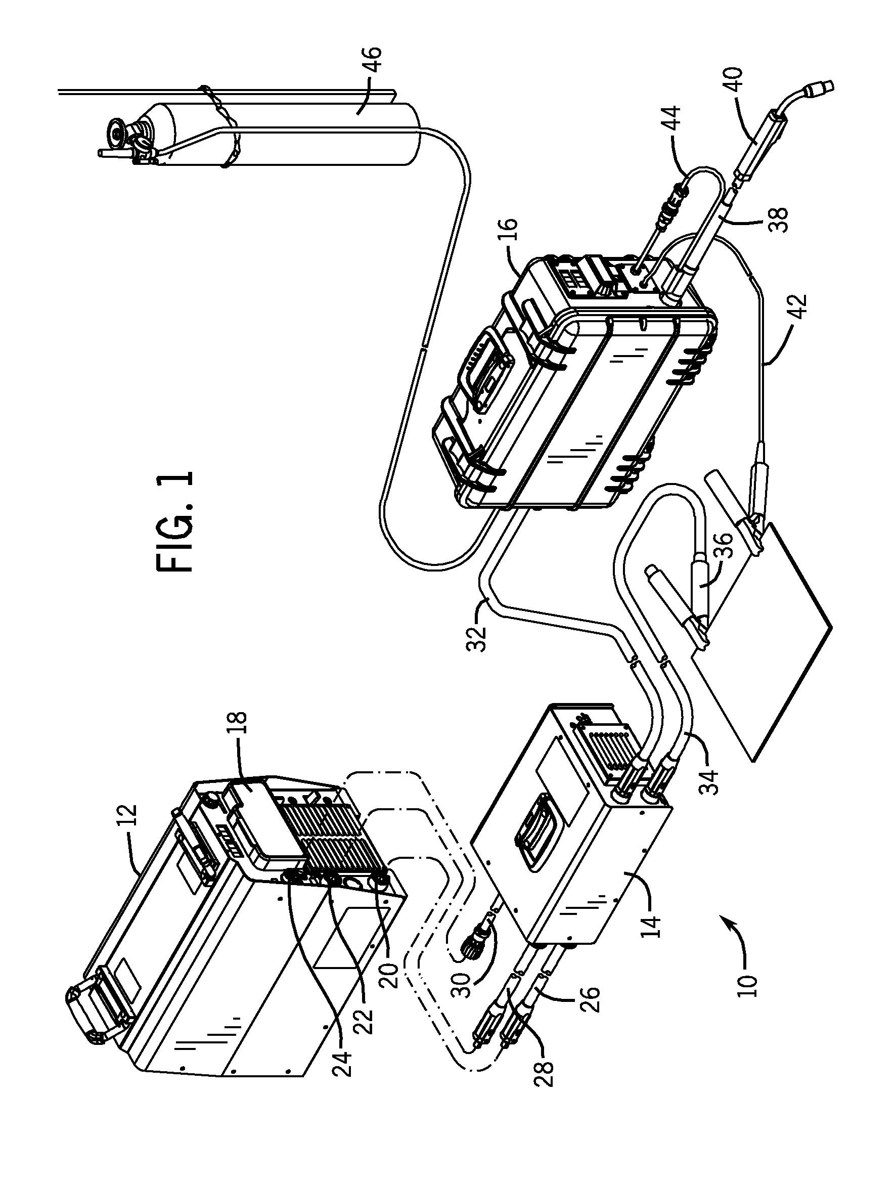
[0014]Turning now to the drawings, and referring first to FIG. 1, a welding system 10 is illustrated that includes a power supply 12, an external control module 14 and a wirefeeder 16. As will be appreciated by those skilled in the art, the system illustrated here is particularly designed for MIG welding, although in practice the power supply 12 may be used for other purposes, such as stick welding or other welding processes. Moreover, in certain designs, the power supply 12 may be designed to receive power from a power grid, or some other power source, or to generate power via an engine-driven generator. In all of these cases, in addition to providing welding power, the power supply may be equipped to provide auxiliary power such as for lights, hand tools, and so forth.

[0015]In the embodiment illustrated, the power supply 12 may be a conventional power supply that ordinarily provides welding power for a welding operation, while exchanging data with a wirefeeder via a separate contr...


PUM

PropertyMeasurementUnit
welding poweraaaaaaaaaa
poweraaaaaaaaaa
voltagesaaaaaaaaaa

Abstract

An external control module is provided for interfacing a welding power supply with a wire feeder. The welding power supply is designed to exchange control signals, feedback signals, and so forth over a control cable when coupled to a standard wire feeder. However, the external control module allows the power supply to be used with a wire feeder that is designed to exchange data combined in a single cable with welding power. The module is coupled to welding and workpiece cables from the power supply, and to a control cable, such as from a multipin connector on the power supply. The module is further coupled to the wire feeder via a welding cable. The module combines data with welding power for transmission to the wire feeder, and extracts data from welding power for application to the power supply.

Description

BACKGROUND[0001]The present invention relates generally to the field of welding systems, and more particularly to welding systems adapted for remote control of welding parameters.[0002]A wide range of systems have been developed and are presently in use for performing welding operations. In general, such devices may be based upon specific technologies and system designs, including metal inert gas (MIG), tungsten inert gas (TIG), stick, and so forth. All of these techniques require a power supply for operation. In such arc welding processes, a power circuit is developed between an electrode and a workpiece, and a resulting arc serves to heat filler metal, base metal or both.[0003]In many welding applications a number of parameters may be modified by user selection on a faceplate or panel on a welding power supply. Such parameters may include selection of a process, selection of currents and voltages, selection of wire feed speeds, and so forth. In some processes the power supply is c...

Claims


Application Information

Patent Timeline
Patent Type & Authority Applications(United States)
IPC IPC(8): B23K11/24
CPCB23K9/095B23K9/124B23K9/1087B23K9/10B23K9/12B23K9/133
Inventor OTT, BRIAN LEE
Owner ILLINOIS TOOL WORKS INC
Why Eureka
Try Eureka