Free-form welded power system component

a technology of power system components and free-form welding, which is applied in the direction of liquid fuel engine components, electric beam welding apparatus, non-positive displacement fluid engine, etc., can solve the problems of inertia, increased production cost and/or complexity of systems with multiple forced induction devices, and limitations in the precision and/or kinds of structures that manufacturing techniques, such as casting, can achiev

Inactive Publication Date: 2006-06-29
CATERPILLAR INC
View PDF18 Cites 54 Cited by
  • Summary
  • Abstract
  • Description
  • Claims
  • Application Information

AI Technical Summary

Benefits of technology

[0007] In one aspect, the present disclosure is directed to a power system component for a work machine. The power system component may include a wheel having one or more free-form welded members. The wheel may include a front end, a back end, and a central, axial spine member extending from the front end to the back end. The wheel may also include an outer shell adjacent the spine member at the front end, extending toward the back end, and flaring radially away from the spine member near the back end. The outer shell may include a front surface and a back surface, and further include one or more protrusions extending from the front surface. The wheel may further include at least one void defined between the spine member and the back surface of the outer shell and at least one reinforcing structure connecting the outer shell with a portion of the spine member between the front end and the back end.
[0008] In another aspect, the present disclosure is directed to a method of manufacturing a power system wheel for a work machine. The method may include melding metal powder in a controlled pattern to form a first layer of the wheel. The method may also include melding one or more additional layers of the metal powder in a controlled pattern, each layer building upon the previous layer to form a central, axial spine member extending from a first end to a second end. Further, the method may also include continuing to meld additional layers to form an outer shell adjacent the spine member at the first end of the wheel, extending toward the second end, and flaring radially away from the spine member near the second end. The outer shell may include a first surface and a second surface, one or more protrusions extending from the first surface, and at least one void defined between the spine member and the second surface of the outer shell.
[0009] In another aspect, the present disclosure is directed to a work machine including a frame, an engine mounted on the frame, and a power system component associated with the engine. The power system component may include a wheel having one or more free-form welded members. The wheel may include a front end, a back end, and a central axial spine member extending from the front end to the back end. The wheel may also include an outer shell extending from the front end toward the back end and flaring away from the spine member near the back end. The outer shell may include a front surface and a back surface, and the wheel may include one or more protrusions extending from the front surface. The wheel may further include at least one void defined between the spine member and the back surface of the outer shell. In addition, the wheel may include at least one reinforcing structure connecting the outer shell with a portion of the spine member between the front end and the back end.

Problems solved by technology

These wheels, however, have mass, and therefore, inertia.
Further, a system with multiple forced induction devices may be more costly and / or complex to produce and maintain.
Some manufacturing techniques, such as casting, have limitations with regard to the precision and / or kinds of structures that they are capable of producing.
Innovative casting techniques have been developed, but may be complicated and / or cumbersome.

Method used


Image

  • Free-form welded power system component
  • Free-form welded power system component
  • Free-form welded power system component

Examples


Embodiment Construction

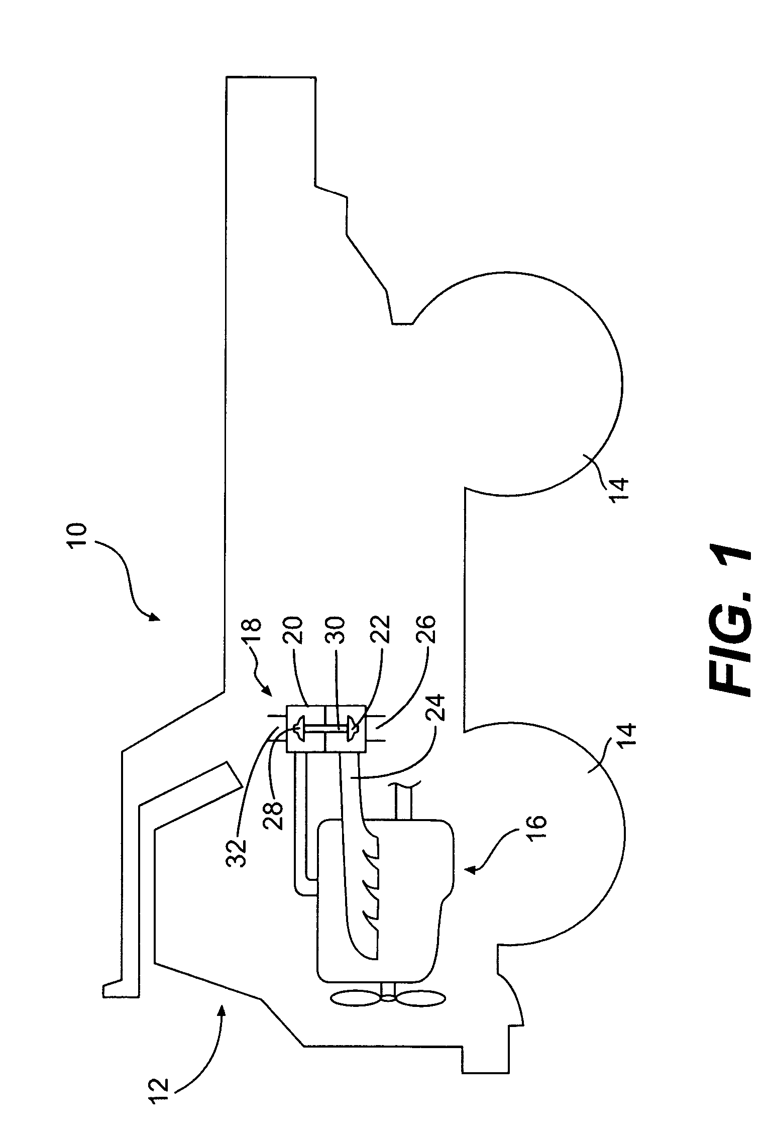
[0017] Reference will now be made in detail to the drawings. Wherever possible, the same reference numbers will be used throughout the drawings to refer to the same or like parts.

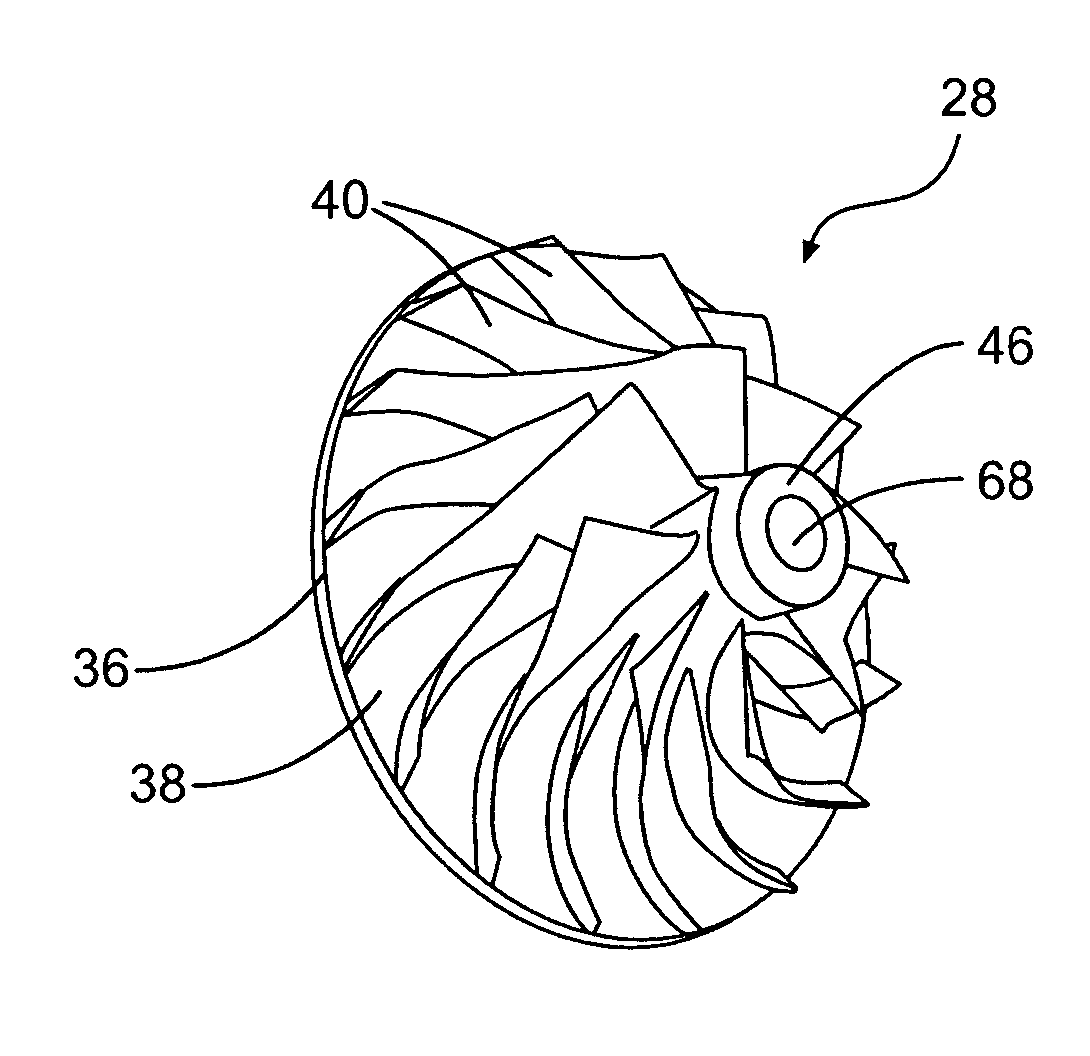
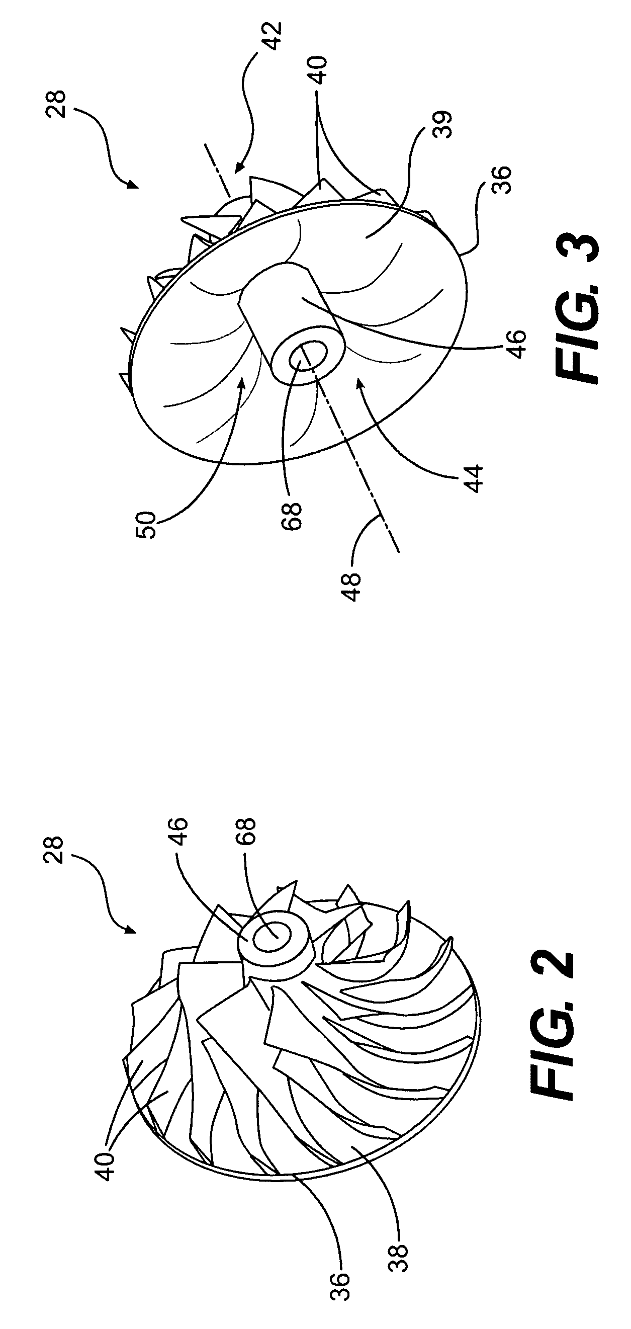
[0018] In one embodiment, one or more parts of a power system component for a work machine (e.g., a compressor wheel or turbine wheel for a forced induction device) may be manufactured by free-form welding. Free-form welding may include assembling a component layer by layer by melding metal powder (e.g., joining at least some of the powder particles together through melting, sintering, fusing, or any other suitable bonding mechanism) in a computer controlled pattern to form each layer. The metal powder may be melded together by any suitable technique, such as, for example, laser sintering, electron beam welding, or any other controlled welding method. In certain embodiments, the entire component may be formed using free-form welding. In other embodiments, only selected portions of the component may be free...


PUM

PropertyMeasurementUnit
latticeaaaaaaaaaa
massaaaaaaaaaa
speedsaaaaaaaaaa

Abstract

The present disclosure is directed to a power system component for a work machine. The power system component may include a wheel having one or more free-form welded members. The wheel may include a front end, a back end, and a central, axial spine member extending from the front end to the back end. The wheel may also include an outer shell adjacent the spine member at the front end, extending toward the back end, and flaring radially away from the spine member near the back end. The outer shell may include a front surface, a back surface, and one or more protrusions extending from the front surface. The wheel may further include at least one void defined between the spine member and the back surface of the outer shell and at least one reinforcing structure connecting the outer shell with a portion of the spine member between the front end and the back end.

Description

TECHNICAL FIELD [0001] The present disclosure is directed to a power system component and, more particularly, to a free-form welded power system component. BACKGROUND [0002] The performance of internal combustion engines may be enhanced with forced induction, such as, for example, supercharging or turbocharging. Forced induction devices, such as superchargers or turbochargers, are essentially air compressors that force more air into the combustion chambers of an engine than the engine could otherwise draw in on its own. With this increased air, more fuel may be injected to create a balanced, but more potent air-fuel mixture. This air-fuel mixture may combust more forcefully, thus enabling the engine to produce more power. [0003] Forced induction devices may include turbine wheels and / or compressor wheels that spin to compress intake air, and thus, increased air flow to the engine. These wheels, however, have mass, and therefore, inertia. The ability to overcome this inertia and get ...

Claims


Application Information

Patent Timeline
Patent Type & Authority Applications(United States)
IPC IPC(8): B64C11/00
CPCB22F3/105B22F5/085B22F5/10B22F7/06B23K15/0046B23K2201/001F01D5/048F02B37/00F04D29/023F04D29/30F04D29/681Y02T50/671Y02T50/673Y02T10/144F05D2230/232F05D2230/31F04D29/284F05D2220/40F05D2230/22B23K2101/001Y02T10/12
Inventor GARMAN, BRIANO'HARA, STEVE
Owner CATERPILLAR INC
Why Eureka
Try Eureka