Electrosurgical device for creating a channel through a region of tissue and methods of use thereof

a tissue region and electrode technology, applied in the field of electrosurgical devices, can solve the problems of not providing an electrode, not disclosing an electrode formed/positioned distal to the electrically and thermally insulating tip,

Active Publication Date: 2011-05-19
BOSTON SCI MEDICAL DEVICE LTD
View PDF32 Cites 86 Cited by
  • Summary
  • Abstract
  • Description
  • Claims
  • Application Information

AI Technical Summary

Benefits of technology

[0016]In one broad aspect, embodiments of the present invention comprise an electrosurgical device for creating a channel through a region of tissue using energy provided by an electrical energy source, the device defining a device proximal region and a device distal region. An electrically conductive elongate member is provided for receiving the energy from the electrical energy source, the elongate member defining a distal end provided in the device distal region. In addition, an electrical insulation layer surrounds the elongate member along the device proximal region. Furthermore, an electrode tip is electrically coupled to the distal end for delivering the energy, the electrode tip being configured and sized for delivering the energy in a manner such that electrical arcing is generated in the region of tissue in order to create a channel through at least a portion of the region of tissue when the electrode tip is positioned proximate the region of tissue. In this context, “proximate” should be understood to mean that the electrode tip is positioned either substantially adjacent to the tissue or slightly spaced apart from the tissue such that a gap exists between the tissue and the electrode tip. The device is further provided with an electrically insulative thermal shield disposed between the electrode tip and the device proximal region for preventing arcing therebetween during the delivery of the energy and for thermally protecting the device proximal region from heat produced by the delivery of the energy through the electrode tip.

Problems solved by technology

However, Rosar et al. do not disclose an electrode that is formed / positioned distal to the electrically and thermally insulating tip.
Thus, the apparatus of Rosar et al. does not provide an electrode for creating a channel in tissue that can allow the device distal end to be advanced without hindrance through the tissue.
Additionally Rosar et al. do not disclose an electrode distal to the insulating tip that secures the tip and allows the tip to be held in place.
However, Langberg does not teach an electrode tip operable to create a channel through tissue.
However, Langberg does not teach a thermal shield for protecting the insulated portion of the catheter.

Method used


Image

  • Electrosurgical device for creating a channel through a region of tissue and methods of use thereof
  • Electrosurgical device for creating a channel through a region of tissue and methods of use thereof
  • Electrosurgical device for creating a channel through a region of tissue and methods of use thereof

Examples


Embodiment Construction

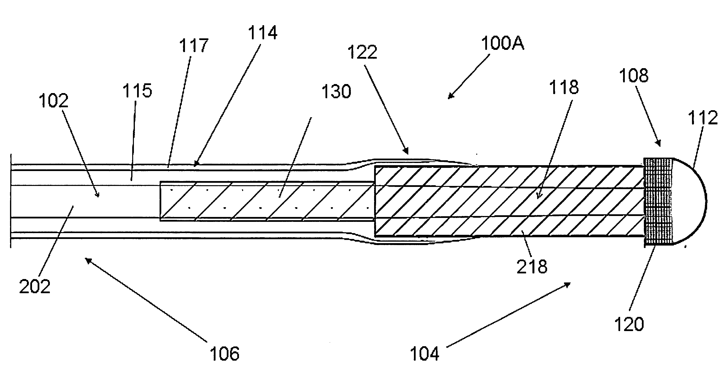
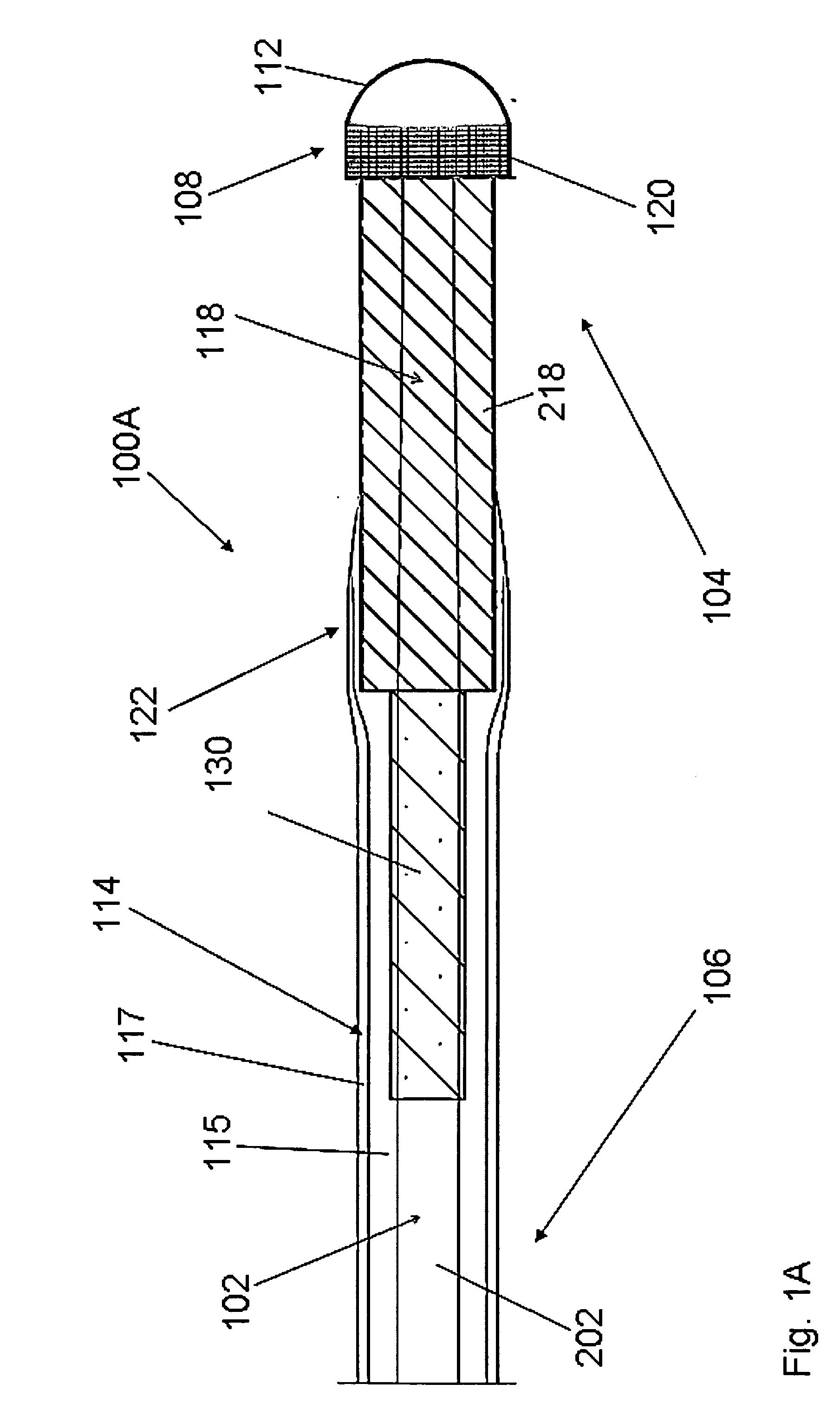
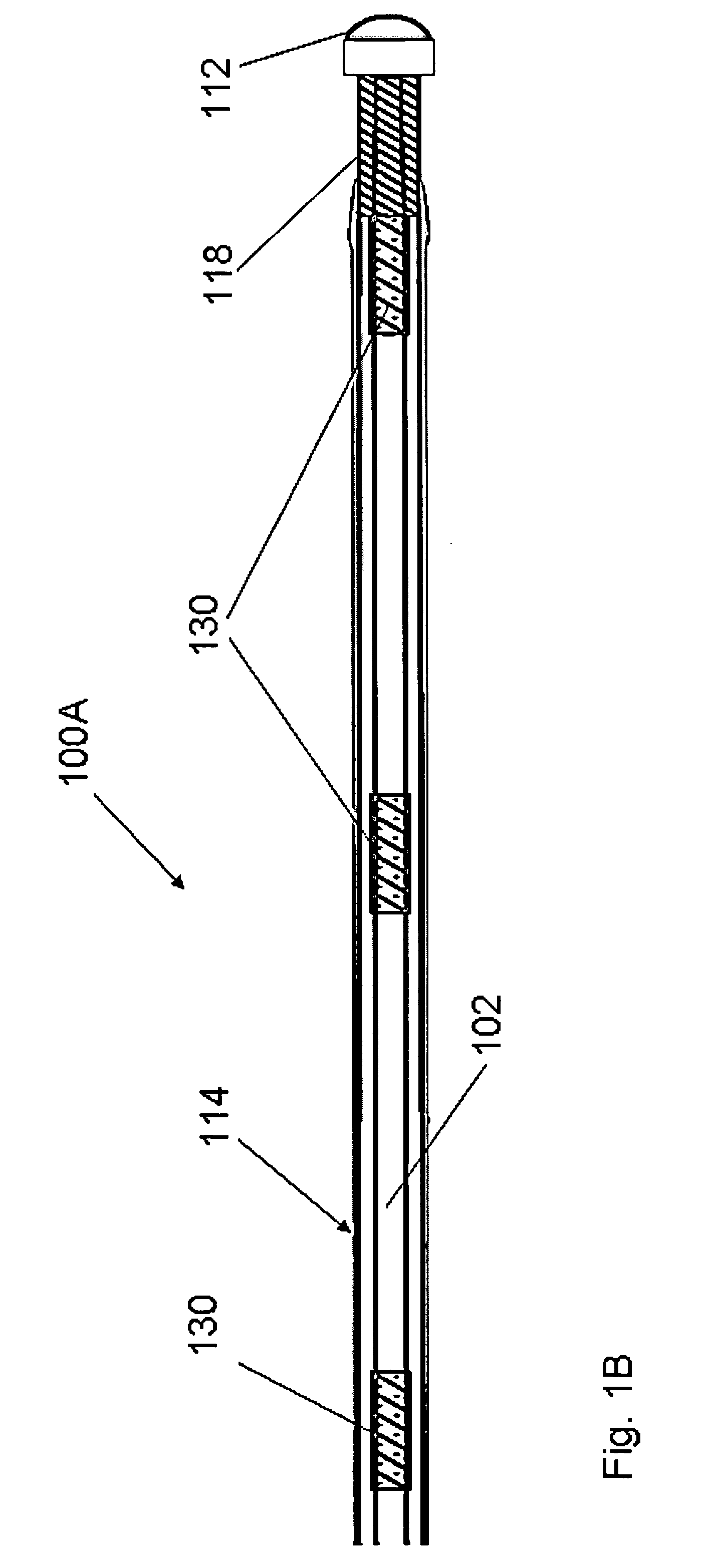
[0040]With specific reference now to the drawings in detail, it is stressed that the particulars shown are by way of example and for purposes of illustrative discussion of certain embodiments of the present invention only. Before explaining at least one embodiment of the invention in detail, it is to be understood that the invention is not limited in its application to the details of construction and the arrangement of the components set forth in the following description or illustrated in the drawings. The invention is capable of other embodiments or of being practiced or carried out in various ways. Also, it is to be understood that the phraseology and terminology employed herein is for the purpose of description and should not be regarded as limiting.

[0041]The description provided herein below for device 100 should be understood by a person skilled in the art to apply to any one of the devices 100A-100E illustrated in the accompanying figures, unless otherwise indicated.

[0042]In ...


PUM

PropertyMeasurementUnit
temperatureaaaaaaaaaa
longitudinal lengthaaaaaaaaaa

Abstract

An electrosurgical device and methods are disclosed for creating a channel through a region of tissue. The device comprises an elongate member for receiving the energy from an electrical energy source. An electrical insulation layer surrounds the elongate member along the device proximal region. An electrode tip is coupled to the distal end of the elongate member for delivering the energy, the electrode tip being configured and sized for delivering the energy in a manner such that electrical arcing is generated in the region of tissue in order to create a channel through at least a portion of the region of tissue. An electrically insulative thermal shield is disposed between the electrode tip and the device proximal region for preventing arcing therebetween during the delivery of the energy and for thermally protecting the device proximal region from heat produced by the delivery of the energy through the electrode tip.

Description

REFERENCES TO PARENT AND CO-PENDING APPLICATIONS[0001]This application is a Continuation-in-part of U.S. patent application Ser. No. 11 / 520,754, filed on Sep. 14, 2006, which is a continuation-in-part of U.S. patent application Ser. No. 11 / 265,304, filed Nov. 3, 2005, which is a continuation-in-part of U.S. application Ser. No. 10 / 666,301, filed Sep. 19, 2003, now U.S. Pat. No. 7,048,733, and which is a continuation-in-part of U.S. application Ser. No. 10 / 760,479, filed Jan. 21, 2004, now U.S. Pat. No. 7,270,662 and which is a continuation-in-part of U.S. application Ser. No. 10 / 666,288, filed Sep. 19, 2003, now abandoned, which is a continuation-in-part of U.S. application Ser. No. 10 / 347,366, filed Jan. 21, 2003, now U.S. Pat. No. 7,112,197. 11 / 520,754 also claims the benefit of U.S. provisional patent application Ser. No. 60 / 596,297, filed Sep. 14, 2005. All of these US patent applications and provisional patent application are hereby incorporated by reference in their entirety.[...

Claims


Application Information

Patent Timeline
Patent Type & Authority Applications(United States)
IPC IPC(8): A61B18/14
CPCA61B18/1492A61B19/54A61B2017/00867C08L2201/12A61B2018/00101A61B2018/00136A61B2018/1213A61B2018/00083A61B90/39A61B2018/0041
Inventor ABOU-MARIE, RUNDJUZKIW, TARASDAVIES, GARETHLUK, MARIALEUNG, RAMSEYMOSLEY, MARKWONG, CHRISTINEALBERT, KELLY
Owner BOSTON SCI MEDICAL DEVICE LTD
Why Eureka
Try Eureka