Blade set for hair clippers

a hair clipper and blade technology, applied in the field of blade sets, can solve the problems of easy injury of users by the movable blade, and achieve the effects of simple and reliable construction, reduced manufacturing costs, and improved safety of hair cutting operations

Inactive Publication Date: 2011-05-26
SPECIALIFE INDS
View PDF7 Cites 29 Cited by
  • Summary
  • Abstract
  • Description
  • Claims
  • Application Information

AI Technical Summary

Benefits of technology

[0015]It is an object of the present invention to provide a new blade set which allows safer hair cutting operation by placing the movable blade assembly in between the upper fixed blade and the lower fixed blade, thus overcoming the disadvantages of the prior art.
[0016]It is another object of the present invention to provide a new blade set which is of simple and reliable construction.
[0017]It is a further object of the present invention to provide a new blade set which is susceptible of a low cost of manufacture with regard to both materials and labor, and which accordingly is then susceptible of low prices of sale to the consuming public, thereby making such blade set economically available to the buying public.

Problems solved by technology

Since the movable blade is exposed to users during the cutting action, it is easy for users to get injured by the movable blade.

Method used


Image

  • Blade set for hair clippers
  • Blade set for hair clippers
  • Blade set for hair clippers

Examples


first embodiment

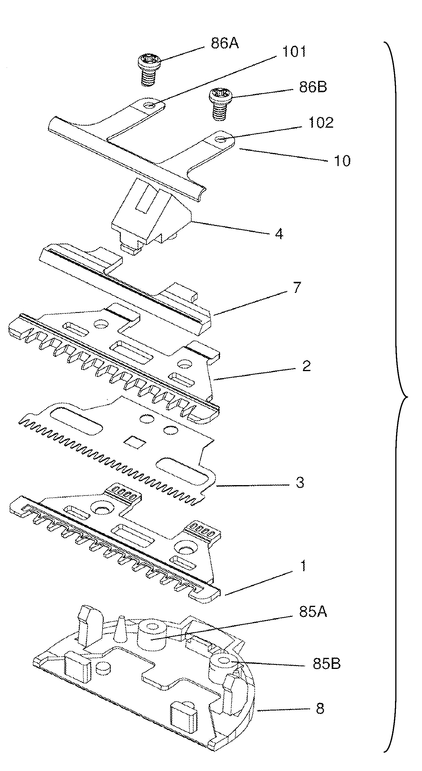
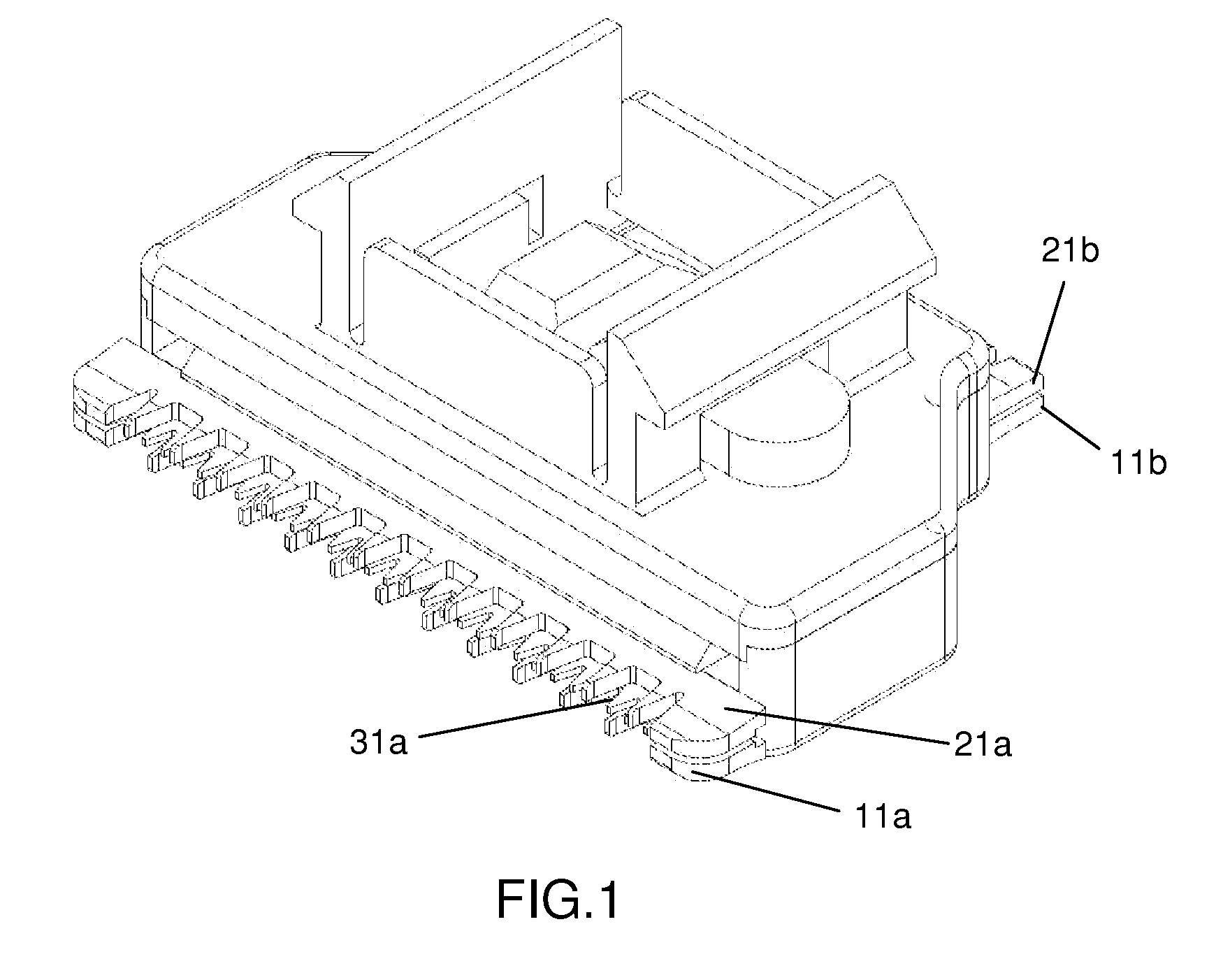
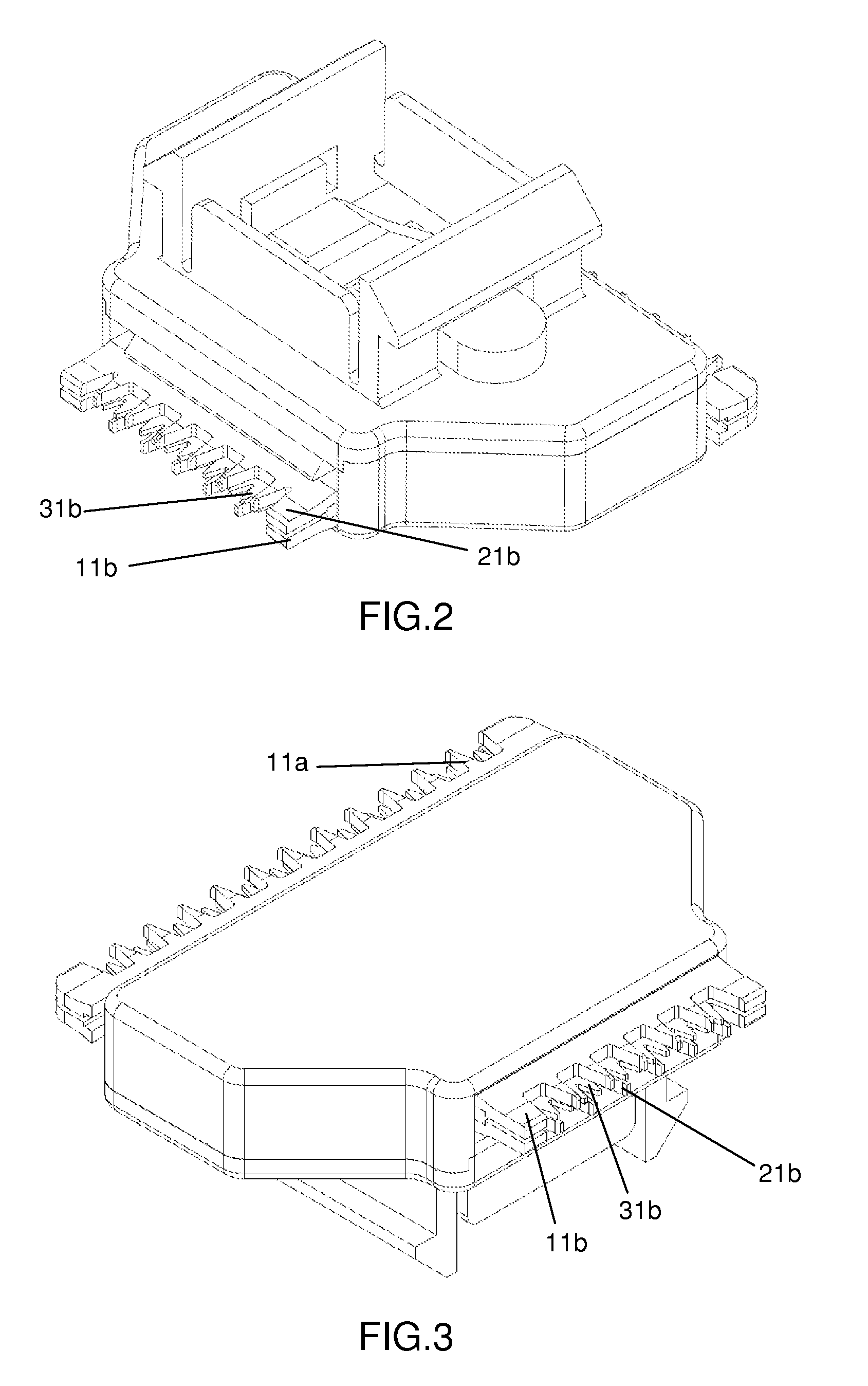
[0036]The present invention is further described in detail with the following embodiments and the accompanying drawings. FIGS. 1 to 7 illustrate the present invention. As illustrated, the present invention comprises a lower fixed blade 1, an upper fixed blade 2, a movable blade assembly 3 and a blade holder 71. The lower fixed blade 1 is provided with a first toothed front edge 11a and a first toothed rear edge 11b opposite thereto. The upper fixed blade 2 is disposed on top of the lower fixed blade 1 and aligned corresponding to the lower fixed blade 1, and is provided with a second toothed front edge 21a and a second toothed rear edge 21b opposite thereto. In this embodiment, the teeth 12a, 22a of the first toothed front edge 11a and the second toothed front edge 12a do not overlap with each other, and the teeth 12b, 22b of the first toothed rear edge 11b and the second toothed rear edge 21b also do not overlap with each other. In other words, at any given time, a strand of hair i...

fourth embodiment

[0042]FIGS. 10 to 14 illustrate the present invention. As illustrated, the present invention comprises a lower fixed blade 1, an upper fixed blade 2, a movable blade assembly 3 and a blade holder 71. The lower fixed blade 1 is provided with a first toothed front edge 11a. The upper fixed blade 2 is provided with a second toothed front edge 21a which is disposed on top of the lower fixed blade 1 and aligned corresponding to the lower fixed blade 1 so that the teeth 12a, 22a of the first toothed front edge 11a and the second toothed front edge 12a do not overlap with each other. In other words, at any given time, a strand of hair is cut either by the cutting surface between the upper fixed blade 2 and the movable blade assembly 3, or by the cutting surface between the lower fixed blade 1 and the movable blade assembly 3, therefore preventing the strand of hair from being pulled simultaneously between the two cutting surfaces and thus reducing the pain caused thereby. Besides, a strand...


PUM


Abstract

A blade set for hair clippers which has a lower fixed blade, an upper fixed blade, a movable blade assembly and a blade holder. The movable blade assembly is flat and extends in a plane parallel to a lengthwise plane of the upper fixed blade and a lengthwise plane of the lower fixed blade and disposed in between the lower fixed blade and the upper fixed blade in such a way that a user's skin is protected from getting injured by the movable blade assembly. A third toothed front edge is provided at a front end of the movable blade assembly, a lower portion of which cooperates with an upper portion of the first toothed front edge to define a first cutting surface, and an upper portion of which cooperates with a lower portion of the second toothed front edge to define a second cutting surface.

Description

BACKGROUND OF THE INVENTION[0001]The present invention relates to a blade set and more particularly pertains to a blade set for hair clippers which has a movable blade disposed between an upper fixed blade and a lower fixed blade and reciprocating laterally relative to the two fixed blades.[0002]Blade sets for hair clippers available in the marketplace generally have a fixed blade and a movable blade. Lateral reciprocation of the movable blade relative to the fixed blade results in a cutting action. Since the movable blade is exposed to users during the cutting action, it is easy for users to get injured by the movable blade.BRIEF SUMMARY OF THE INVENTION[0003]In view of the aforesaid disadvantages now present in the prior art, the present invention provides a blade set for hair clippers which has one movable blade assembly disposed between an upper fixed blade and a lower fixed blade and reciprocating laterally relative to the two fixed blades. Since the movable blade assembly is c...

Claims


Application Information

Patent Timeline
Patent Type & Authority Applications(United States)
IPC IPC(8): B26B19/06
CPCB26B19/06
Inventor LAU, TUNG YAN
Owner SPECIALIFE INDS
Why Eureka
Try Eureka