Band saw

a band saw and saw blade technology, applied in the field of power tools, can solve the problems of difficult operation for users difficulty in a user's operation in a variety of cutting applications, and often in need of replacement or repair of the housing

Inactive Publication Date: 2011-05-26
MILWAUKEE ELECTRIC TOOL CORP
View PDF106 Cites 17 Cited by
  • Summary
  • Abstract
  • Description
  • Claims
  • Application Information

AI Technical Summary

Benefits of technology

The invention provides, in another aspect, a band saw including a housing having a deck and a guard. A motor and a gear box are mounted to the deck. A first wheel is supported by the housing for rotation about a first wheel axle, the first wheel being coupled to the motor and drivable by the motor, and a second wheel is supported by the housing for rotation about a second wheel axle. A band saw blade extends around the first wheel and the second wheel and travels in a continuous loop around the wheels to cut a work piece. The wheels are coupled to axles mounted within housing on the deck, and the guard is positioned between the deck and the wheels. The guard is positioned around at least a portion of a perimeter of the band saw and adjacent at least a portion of the band saw blade to protect the band saw blade from external hazards.

Problems solved by technology

For instance, band saws may be large and heavy, which may be difficult for a user to operate in a variety of cutting applications.
The housing endures bumps and scratches caused by the user, and therefore the housing is often in need of replacement or repair.

Method used


Image

  • Band saw
  • Band saw
  • Band saw

Examples


Embodiment Construction

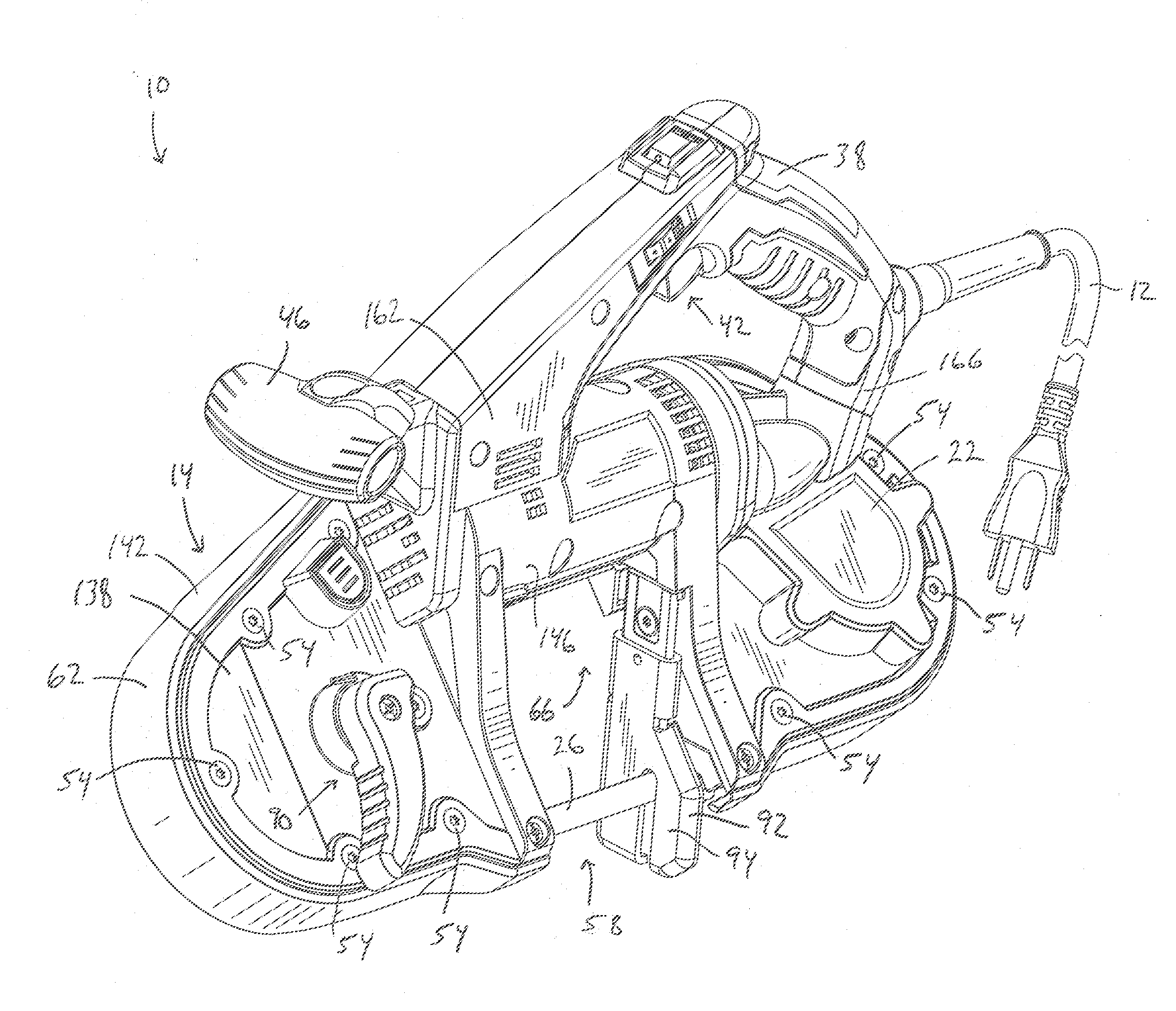
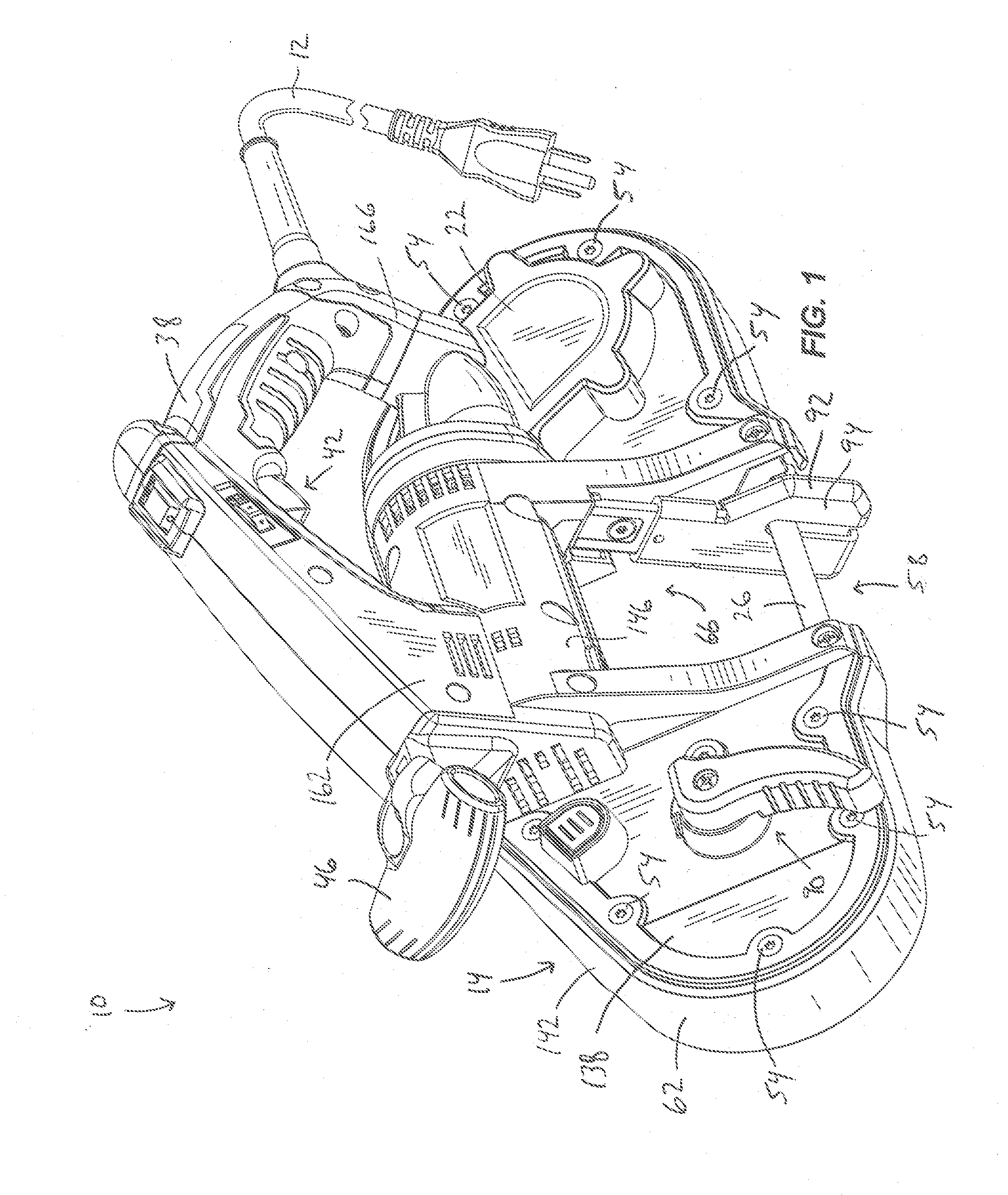
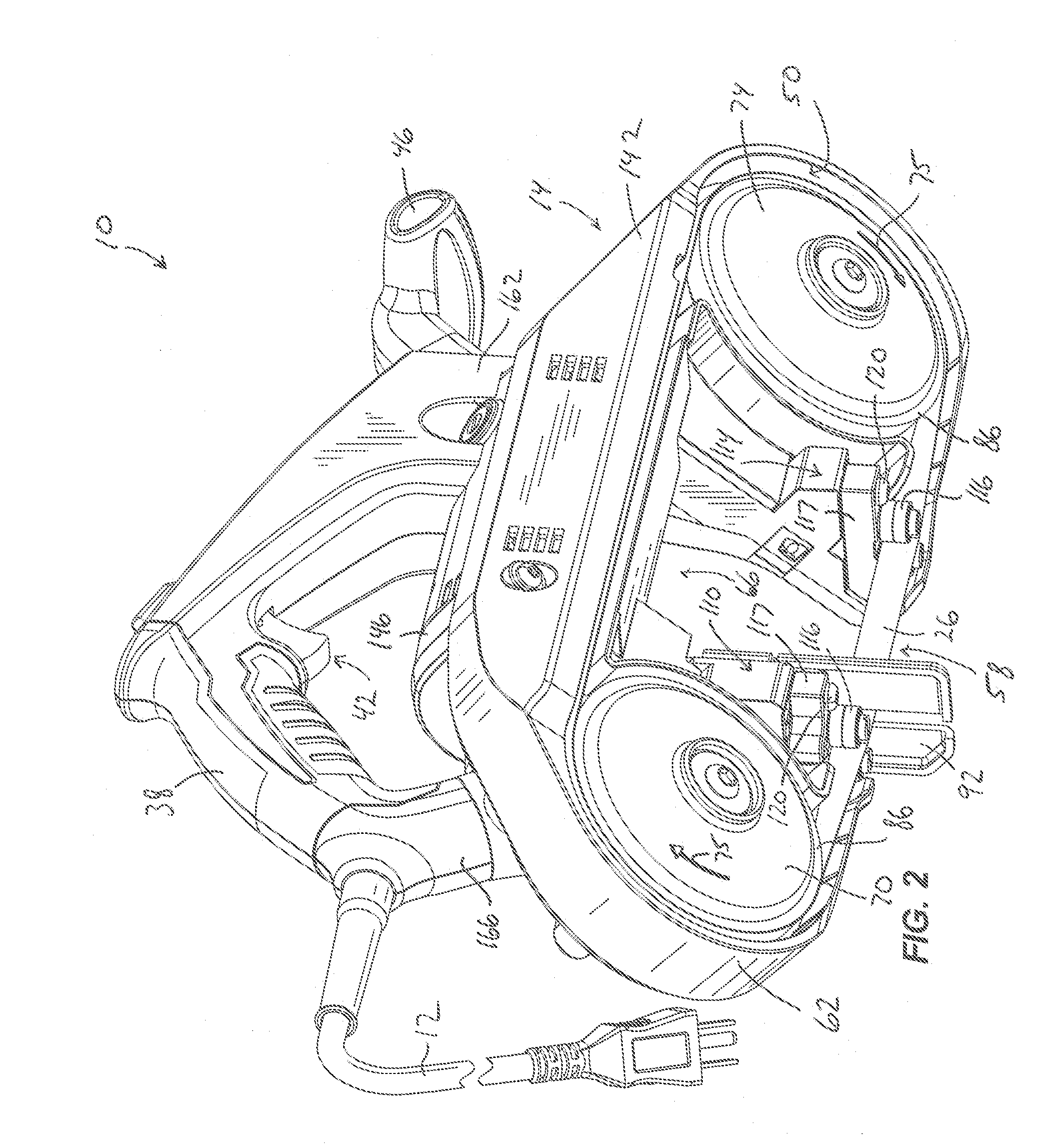
FIGS. 1-11 illustrate a band saw 10 including a frame or housing 14 supporting a motor 18 and a gear box 22. In the illustrated construction of the band saw 10, the motor 18 (FIG. 10) is configured as an AC motor, and the band saw 10 includes an electrical connection cord 12 connectable to a source of AC power (e.g., a household electrical outlet) to deliver AC power to the motor 18. The motor 18 is drivingly connected to a drive assembly (not shown) at least partially housed within the gear box 22. The drive assembly may include any of a number of different gear train arrangements configured to provide a low-speed, high-torque output from the high-speed, low-torque input provided by the motor 18. The motor 18 and the drive assembly are operable to drive a continuous band saw blade 26 to cut a work piece.

With reference to FIGS. 1-3, the housing 14 includes a main handle 38 supporting a switch assembly 42 to provide power to the band saw 10. The switch assembly 42 is operable to cont...


PUM

PropertyMeasurementUnit
diameteraaaaaaaaaa
distanceaaaaaaaaaa
spacing distance D2aaaaaaaaaa

Abstract

A hand-held power tool includes a housing having an opening, first and second wheels supported by the housing for rotation about respective first and second parallel axes, a continuous saw blade supported by the first and second wheels, a first guide roller set coupled to the housing proximate a first side of the opening, and a second guide roller set coupled to the housing proximate a second side of the opening. The first and second wheels define respective first and second facing, parallel planes containing the first and second axes. The first and second guide roller sets define respective third and fourth facing, parallel planes that are also parallel to the first and second planes. A first dimension between the first plane and the third plane is less than about 3.3 inches. A second dimension between the second plane and the fourth plane is less than about 3.3 inches.

Description

BACKGROUND OF THE INVENTIONThe present invention relates to power tools, and more particularly to band saws.Band saws are generally configured with various sizes to accommodate different cutting applications. For instance, band saws may be large and heavy, which may be difficult for a user to operate in a variety of cutting applications. Band saws may have a 4.75-square inch cutting capacity or as little as 2.5-square inch cutting capacity. The spacing distance, or the distance between an axis of rotation of a pulley wheel and a center point of a guide roller set on a non-compact band saw is approximately 3.3 inches. The twist rate, or the amount of twist of the band saw blade from a perpendicular position to a cutting position on a band saw is approximately 15.15 degrees per inch (i.e., 50 degree twist over a distance of 3.3 inches).In addition, band saws typically include a housing surrounding at least an outer circumference of the band saw blade. The housing protects a user from ...

Claims


Application Information

Patent Timeline
Patent Type & Authority Applications(United States)
IPC IPC(8): B23D53/12
CPCB23D53/12B23D55/082B23D55/00
Inventor BERTSCH, MATTHEW T.ELGER, WILLIAM A.
Owner MILWAUKEE ELECTRIC TOOL CORP
Why Eureka
Try Eureka