Unit for locking ring sectors on a turbomachine casing, comprising radial passages for gripping it

Active Publication Date: 2011-05-26
SN DETUDE & DE CONSTR DE MOTEURS DAVIATION S N E C M A
View PDF11 Cites 6 Cited by
  • Summary
  • Abstract
  • Description
  • Claims
  • Application Information

AI Technical Summary

Benefits of technology

[0012]The special positions of the passages at the connecting arm, namely at a distance from the forward ends of the clamping arms that squeeze the ring sectors into contact, means that they can easily cooperate with an extraction tool without any risk of adversely affecting the functions of this locking unit, therefore particularly due to the lack of direct contact between the tool and the above-mentioned ends.
[0015]Preferably, the two passages are arranged on or close to said first circumferential end and said second circumferential end. These ends are in the least highly stressed portions of the unit when the unit is in the ring sector clamping condition, such that the presence of passages at these locations only negligibly weakens the unit, and surrounding zones do not need to be oversized.

Problems solved by technology

In such cases it is extremely difficult to extract these locking units, for example when necessary during turbine maintenance operations, due to the high radial clamping force applied by the longitudinal arms on the circumferential rims.
Consequently, in order to make the extraction, the operator usually needs to use an unsuitably shaped tool that might damage the locking units and surrounding elements.
The screwdriver is then used as a lever arm and might damage both the longitudinal arm and the circumferential rim concerned, or even injure the operator.
Consequently, the design of existing locking units does not enable fast and easy extraction, and also generates serious risks of damaging clamping arms during this extraction.

Method used


Image

  • Unit for locking ring sectors on a turbomachine casing, comprising radial passages for gripping it
  • Unit for locking ring sectors on a turbomachine casing, comprising radial passages for gripping it
  • Unit for locking ring sectors on a turbomachine casing, comprising radial passages for gripping it

Examples


Embodiment Construction

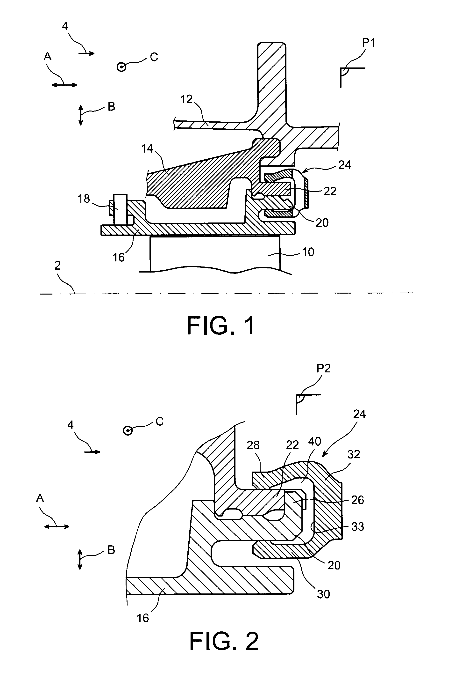
[0035]FIGS. 1 and 2 show an overview of a device for the attachment of ring sectors onto a turbine casing of an aircraft turbomachine according to one preferred embodiment of this invention.

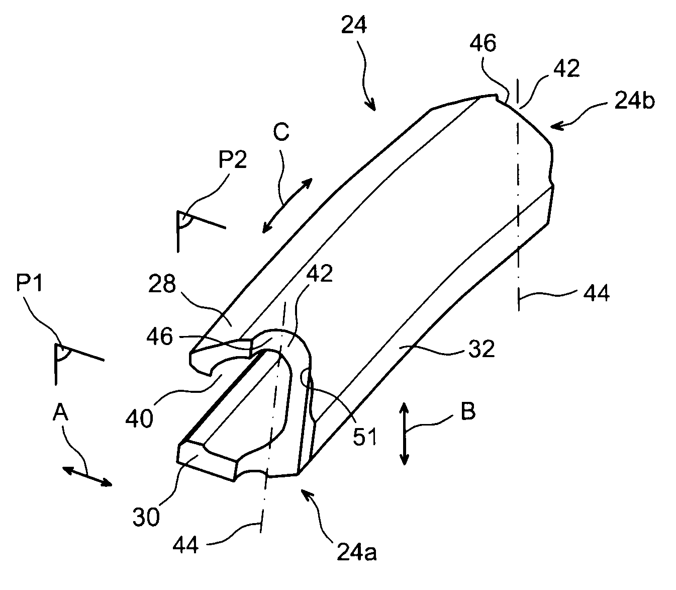
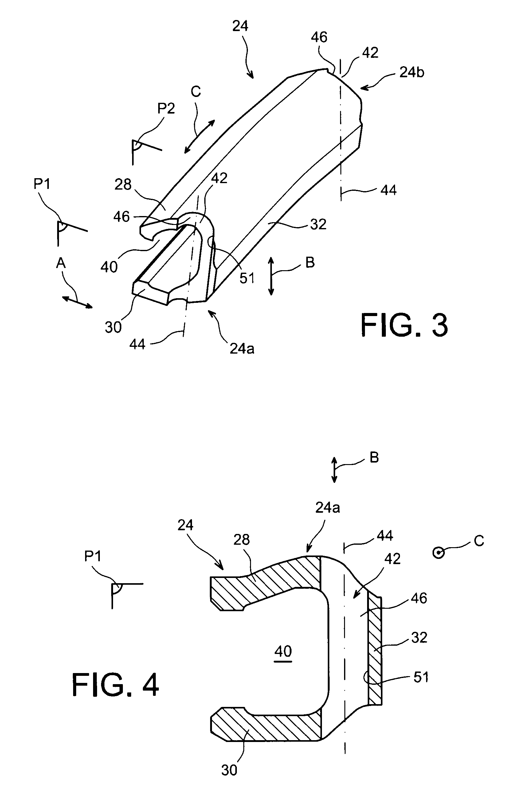
[0036]On the figures, direction A corresponds to the longitudinal or axial direction parallel to the longitudinal axis 2 of the turbine and the turbomachine. Direction B corresponds to the radial direction of the turbine, and direction C to the circumferential direction. The arrow 4 also diagrammatically shows the main gas flow direction within the turbomachine, parallel to direction A, the terms >, >, >, > used in the remainder of this description being used relative to a forward direction of movement of the aircraft under the thrust of the turbomachine, this forward direction of movement being in the direction opposite to the arrow 4.

[0037]Reference 10 in FIG. 1 denotes the mobile blades of a high pressure turbine stage of a turbojet that rotate in a turbine casing 12 inside which casing elemen...


PUM

PropertyMeasurementUnit
Shapeaaaaaaaaaa

Abstract

A unit locking a ring sector attachment device onto an aircraft turbomachine casing, the unit including two clamping arms connected to each other at their aft ends by a connecting arm extending approximately parallel to the general direction between the two clamping arms. The unit also includes a passage enabling gripping of the unit on each side of a fictitious median plane orthogonal to the circumferential direction, each passage being formed in the connecting arm, extending along a direction line approximately parallel to the direction between the arms.

Description

TECHNICAL DOMAIN[0001]This invention relates in general to a unit for locking a ring sector attachment device onto an aircraft turbomachine, for example a turbine casing.[0002]The invention also relates to a turbomachine for an aircraft fitted with such locking units, this turbomachine possibly being in the form of a turboprop or a turbojet.STATE OF PRIOR ART[0003]Ring sectors fixed circumferentially on the casing around the mobile blades of the turbine of a turbojet and jointly forming a continuous cylindrical envelope delimiting the outside boundary of the gas path in the turbine, are known in prior art. The ring sectors are mounted on an internal casing of the turbine by means of casing elements called intermediate casing elements or spacers, onto which they are attached at their forward end and they are held in place at their aft end by C-shaped or horizontal U-shaped locking units. The aft ends of these locking units are axially / longitudinally engaged on circumferential rims of...

Claims


Application Information

Patent Timeline
IPC IPC(8): F16B2/10F01D25/24
CPCF05D2230/70F01D25/246Y10T29/49323F16B2/245Y02T50/672F05D2230/60Y02T50/60
Inventor GENDRAUD, ALAIN DOMINIQUE
Owner SN DETUDE & DE CONSTR DE MOTEURS DAVIATION S N E C M A
Why Eureka
Try Eureka