Improved fire resistance device designed to be placed between one end of a mounting strut for an aircraft turbomachine and a cowling of said turbomachine delimiting an inter-flow compartment

Pending Publication Date: 2021-04-29
SN DETUDE & DE CONSTR DE MOTEURS DAVIATION S N E C M A
View PDF0 Cites 0 Cited by
  • Summary
  • Abstract
  • Description
  • Claims
  • Application Information

AI Technical Summary

Benefits of technology

[0021]Preferably, the support portion carries elongated attachment elements, opposite the second lip and its protection zone. These elongated attachment elements can then easily cooperate with the connection cowling, for better retention on this cowling.
[0022]Preferably, the device is formed by the superposition of at least one layer of elastomer material, preferably a silicone elastomer, and at least one fibrous layer, preferably made of ceramic, glass or meta-aramid (poly(m-phenylene isophthalamide))

Problems solved by technology

The problem of the fire resistance function then arises, because it is required to prevent the propagation of a flame initiating in t

Method used


Image

  • Improved fire resistance device designed to be placed between one end of a mounting strut for an aircraft turbomachine and a cowling of said turbomachine delimiting an inter-flow compartment
  • Improved fire resistance device designed to be placed between one end of a mounting strut for an aircraft turbomachine and a cowling of said turbomachine delimiting an inter-flow compartment
  • Improved fire resistance device designed to be placed between one end of a mounting strut for an aircraft turbomachine and a cowling of said turbomachine delimiting an inter-flow compartment

Examples


Example

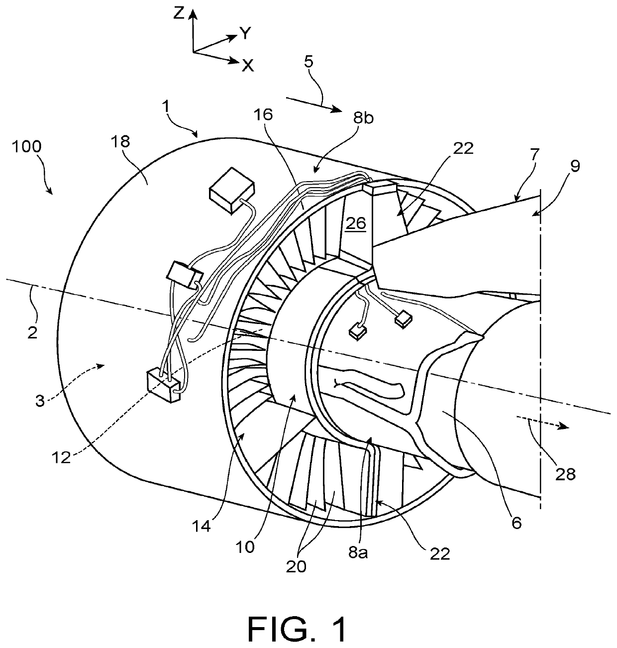
[0050]Firstly with reference to FIG. 1, the figure shows a partial view of a propulsion assembly 100 according to a preferred embodiment of the invention. This assembly 100 comprises a twin-spool turbomachine 1 for an aircraft, and a mounting strut 9 for this turbomachine on a wing element of the aircraft (not represented).

[0051]The propulsion assembly 100 has a longitudinal direction X, also corresponding to the longitudinal direction of the turbomachine 1 and to the longitudinal direction of the mounting strut 9. The assembly 100 also has a transverse direction Y, and a vertical direction Z, corresponding to the direction of the height. The three directions X, Y and Z are orthogonal to each other and form a right-handed trihedron.

[0052]Preferably, the mounting strut 9 is used to suspend the turbomachine 1 under a wing of the aircraft. This mounting strut comprises a structural part that will resist forces from the turbomachine, this part normally being called the primary structure...


PUM


Abstract

A fire resistance device designed to be placed between a mounting strut of a double-flow aircraft turbomachine and a connecting cowling with which the turbomachine is equipped, the connecting cowling being designed to connect an upstream ring, delimiting an inter-flow compartment, to an arm that extends radially across a secondary flow of the turbomachine. The device can be produced as a single piece and includes two contact lips which extend along different lines, the first lip having a C-shaped cross-section.

Description

TECHNICAL FIELD[0001]The invention relates to the fire resistance function between an inter-flow compartment of a twin-spool turbomachine for an aircraft and a zone upstream from the mounting strut of this turbomachine. In particular, it aims to prevent a fire initiated in the inter-flow compartment from propagating in the zone upstream from the mounting strut.[0002]The invention is applicable to all types of twin-spool turbine engines, and particularly to a turbojet.STATE OF PRIOR ART[0003]In a twin-spool turbomachine for an aircraft, there are usually one or several arms that pass radially through the fan flow stream, downstream from the fan. This arm is typically arranged so as to connect a fan compartment located around the outer shroud of an intermediate casing, to an inter-flow compartment. Conventionally, these two compartments house equipment and auxiliaries, while the arm placed between the two provides the passage for different elements such as electrical cables, and / or fl...

Claims


Application Information

Patent Timeline
IPC IPC(8): B64D27/26F02C7/20
CPCB64D27/26F02C7/25F02C7/20B64D2045/009F05D2230/53F05D2240/55Y02T50/60B64D27/18F02C7/28F05D2220/323F05D2240/90
Inventor JACON, BRUNO ALEXANDRE DIDIERACHBARI, BAGHDADSIMONOTTI, HERVÉ
Owner SN DETUDE & DE CONSTR DE MOTEURS DAVIATION S N E C M A
Why Eureka
Try Eureka