
Imaging apparatus, image processing method, and computer program product

Active Publication Date: 2011-05-26
RICOH KK
View PDF8 Cites 6 Cited by
  • Summary
  • Abstract
  • Description
  • Claims
  • Application Information

AI Technical Summary

Benefits of technology

[0010]It is an object of the present invention to at least partially solve the problems in the conventional technology.

Problems solved by technology

Hence, using an AF evaluation value in weighting a motion vector per region tends to cause false detection when there is relative motion in an edge direction between an imaging apparatus and a subject.

Method used


Image

  • Imaging apparatus, image processing method, and computer program product
  • Imaging apparatus, image processing method, and computer program product
  • Imaging apparatus, image processing method, and computer program product

Examples


Embodiment Construction

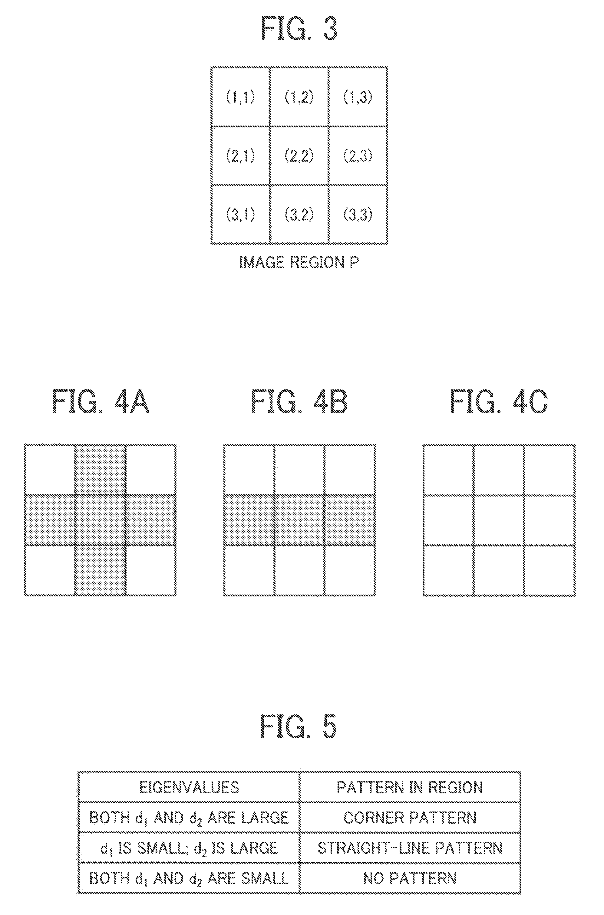
[0023]Exemplary embodiments of the present invention are described below with reference to the accompanying drawings. In the embodiments described herein, a “straight-line pattern” refers to a pattern of a straight line formed of an edge portion of an object or the like included in an image.

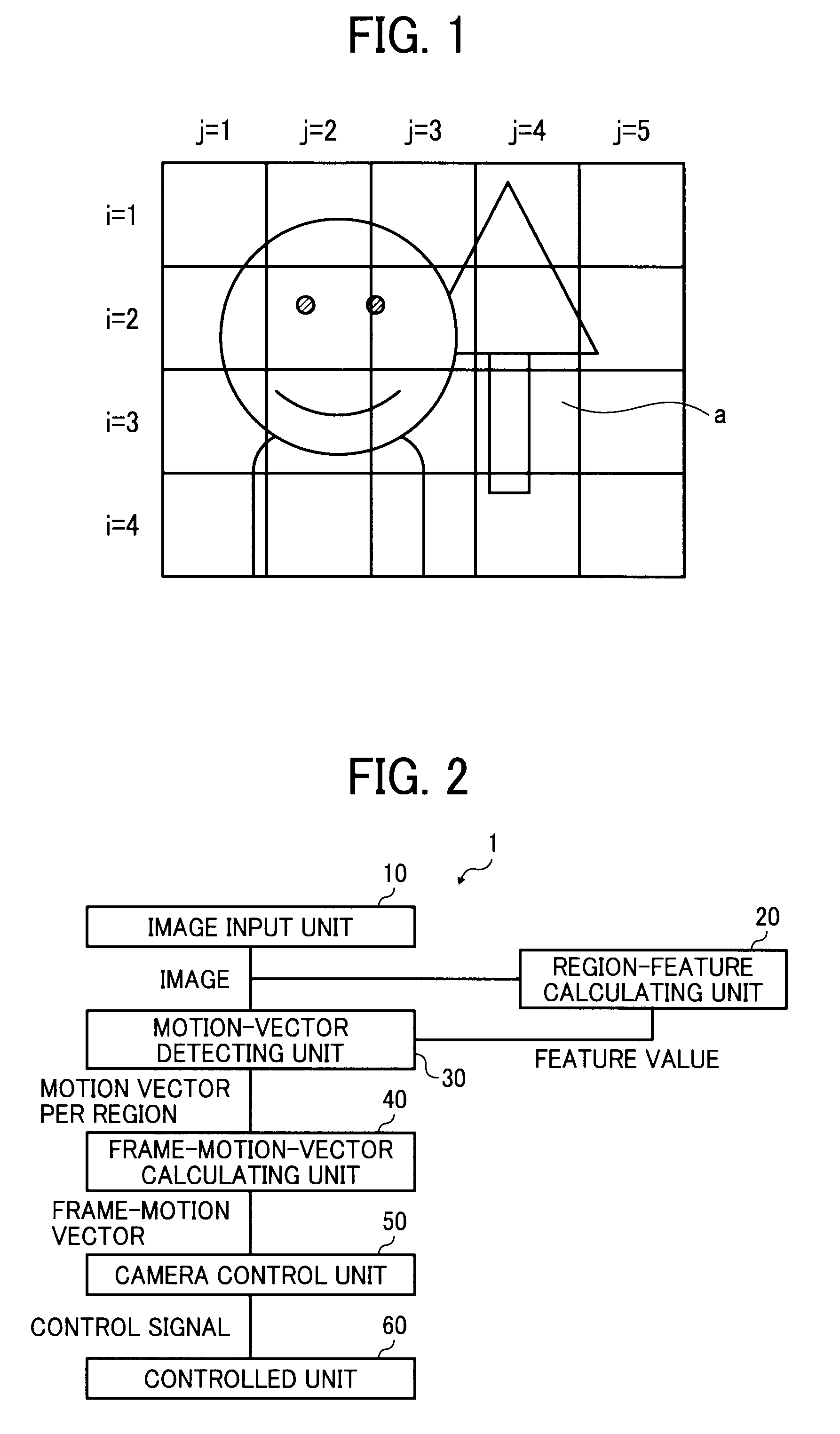
[0024]FIG. 1 is a diagram of an example of an image obtained by an imaging apparatus according to an embodiment of the present invention. The image in FIG. 1 is divided into four rows of i=1 to 4 and five columns of j=1 to 5, and thus has a total of 20 regions.

[0025]In the image in FIG. 1, a region “a” of (i=3, j=4), for example, includes a straight-line pattern. In motion detection with respect to the region “a”, faults may occur, such as no motion being detected when there is relative motion between an imaging apparatus and a subject in a same direction as a direction in which a straight line extends, or motion being detected when there is actually no relative motion.

[0026]In the present embodi...


PUM


Abstract

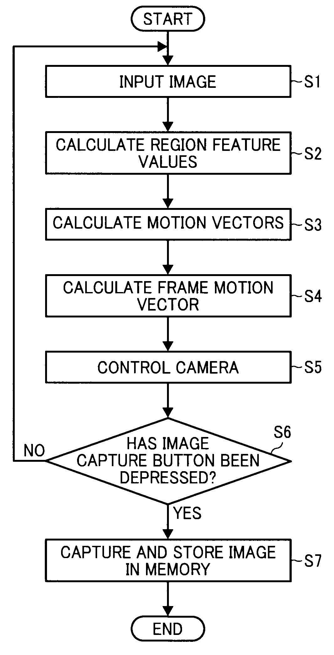
An imaging apparatus includes: an imaging unit that captures an image by photoelectrically converting a subject image; a feature calculating unit that calculates, per region included in the image, a feature value related to suitability for motion detection; a region-motion detecting unit that detects a motion vector per the region; and a whole-motion calculating unit that calculates a motion quantity of a whole image from the feature value and the motion vector.

Description

CROSS-REFERENCE TO RELATED APPLICATIONS[0001]The present application claims priority to and incorporates by reference the entire contents of Japanese Patent Application No. 2009-265951 filed in Japan on Nov. 24, 2009 and Japanese Patent Application No. 2010-123530 filed in Japan on May 28, 2010.BACKGROUND OF THE INVENTION[0002]1. Field of the Invention[0003]The present invention is directed generally to an imaging apparatus, an image processing method, and a computer program product.[0004]2. Description of the Related Art[0005]Conventionally, there are techniques for detecting a motion vector of a whole image to perform correction of blurring associated with motion of a digital camera by movement of a user's hands. For instance, an invention is disclosed in Japanese Patent Application Laid-open No. 2006-287814, which relates to an imaging apparatus or the like that uses an AF value of each region when evaluating a motion vector per region obtained by dividing a frame of a subject in...

Claims


Application Information

Patent Timeline
IPC IPC(8): G06K9/40H04N5/225
CPCG06T7/2013H04N5/23248G06T2207/20012G06T7/223H04N23/68
Inventor YAMANAKA, YUJIGUAN, HAIKE
Owner RICOH KK
Learn More