Control apparatus and control method for vehicle automatic transmission

a control apparatus and automatic transmission technology, applied in mechanical apparatus, digital data processing details, instruments, etc., can solve the problems of difficult to improve the drive power response, the output torque is not increased, and the drive power response cannot be separately controlled, so as to reduce the synchronization shock, the drive power response is improved, and the drive power response is not decreased.

Active Publication Date: 2011-05-26
TOYOTA JIDOSHA KK
View PDF24 Cites 6 Cited by
  • Summary
  • Abstract
  • Description
  • Claims
  • Application Information

AI Technical Summary

Benefits of technology

[0013]In other words, because the torque is transmitted through the predetermined friction engagement device, which is used to achieve the second predetermined gear, the rotational direction of the one-way clutch is changed at a low rate toward the rotational direction in which the one-way clutch is brought to the synchronized state, as compared to the case where the rotational direction of the one-way clutch is changed toward the rotational direction in which the one-way clutch is brought to the synchronized state, according to the accelerkion request, when the torque is not transmitted through the predetermined friction engagement device. Thus, it is possible to suppress the synchronization shock. In this case, the synchronization of the one-way clutch is delayed ...

Problems solved by technology

That is, the drive power response and the synchronization shock cannot be separately controlled.
Accordingly, it may be difficult to improve the drive power response, and to reduce the synchronization shock at the same time, depending o...

Method used


Image

  • Control apparatus and control method for vehicle automatic transmission
  • Control apparatus and control method for vehicle automatic transmission
  • Control apparatus and control method for vehicle automatic transmission

Examples


Embodiment Construction

[0041]Hereinafter, an embodiment of the invention will be described in detail with reference to the drawings.

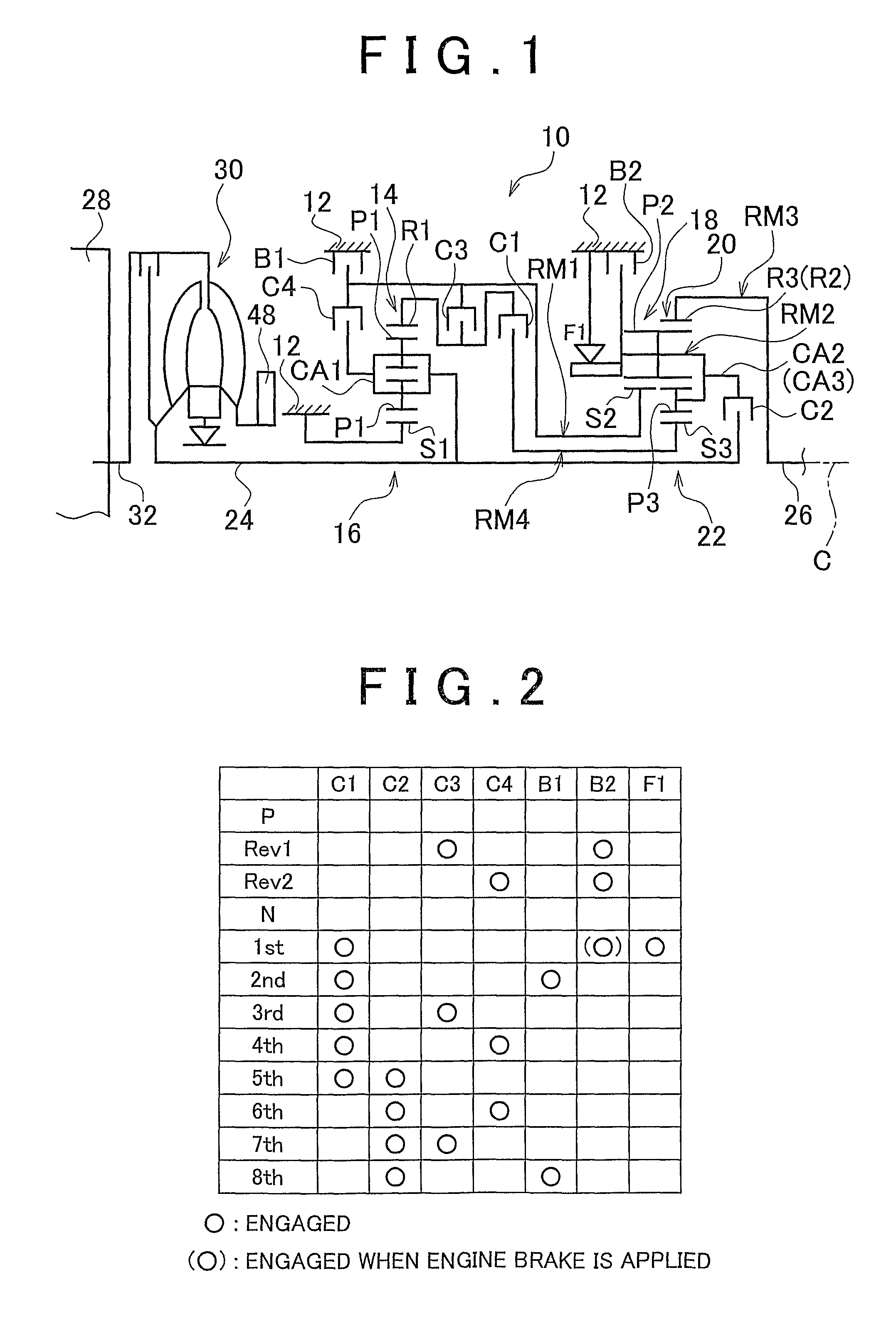
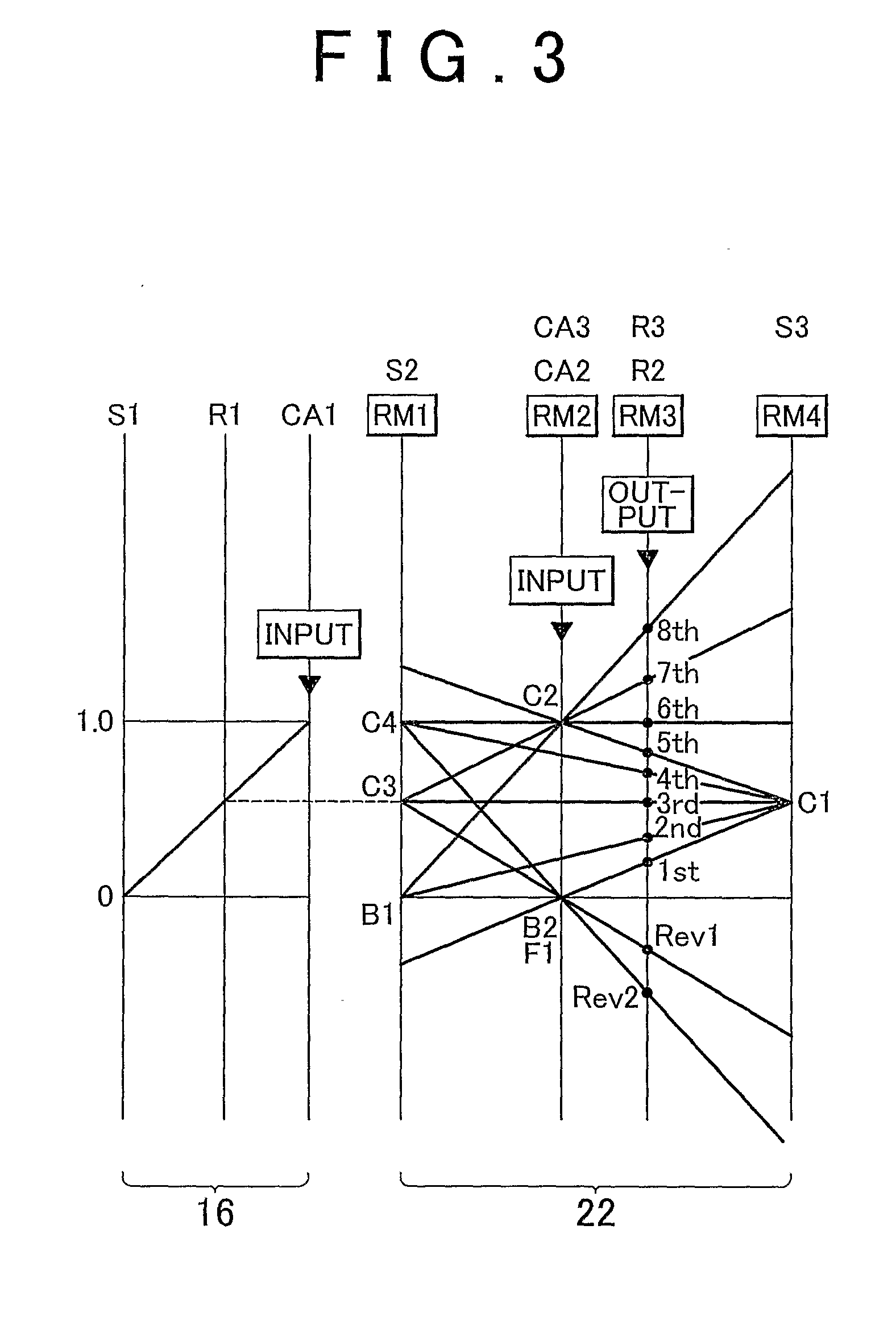
[0042]FIG. 1 is a schematic diagram showing a configuration of a vehicle automatic transmission (hereinafter, simply referred to as “automatic transmission”) 10, to which the invention is applied. The automatic transmission 10 includes a first shift portion 16 and a second shift portion 22 that are provided on a common axis C in a transmission case (hereinafter, simply referred to as “case”) 12. The transmission case 12, which is a non-rotational member, is fitted to a vehicle body. The first shift portion 16 mainly includes a first planetary gear unit 14 of a double pinion type. The second shift portion 22 mainly includes a second planetary gear unit 18 of a single pinion type and a third planetary gear unit 20 of a double pinion type. The automatic transmission 10 changes the speed of the rotation input from an input shaft 24, and outputs the rotation from an output shaft 2...


PUM


Abstract

In a control apparatus and a control method for a vehicle automatic transmission in which a plurality of gears with different speed ratios are achieved by selectively engaging a plurality of friction engagement devices and a one-way clutch, if an acceleration request is made in the case where the one-way clutch is in an idling state when a first predetermined gear is to be achieved by engaging the one-way clutch, a pre-synchronization control is executed to transmit torque through a predetermined friction engagement device used to achieve a second predetermined gear at which the one-way clutch is maintained in an idling state, and to continue to change a rotational direction of the one-way clutch toward a rotational direction in which the one-way clutch is brought to a synchronized state, according to the acceleration request.

Description

BACKGROUND OF THE INVENTION[0001]1. Field of the Invention[0002]The invention relates to a control apparatus and a control method for a vehicle automatic transmission, in which a plurality of gears are selectively achieved, the plurality of gears including a gear that is achieved by engaging a one-way clutch. More specifically, the invention relates to a technology for suppressing a shock when a one-way clutch is brought to a synchronized state.[0003]2. Description of the Related Art[0004]A vehicle, which includes an automatic transmission in which a plurality of gears with different speed ratios are achieved by selectively engaging a plurality of friction engagement devices and a one-way clutch, is available. In the vehicle, power output from a drive power source, such as an engine, is transmitted to drive wheels via the automatic transmission. In the vehicle, when the one-way clutch is brought to the synchronized state (that is, when the one-way clutch, which has been in an idling...

Claims


Application Information

Patent Timeline
IPC IPC(8): F16H59/48
CPCF16H61/0403F16H61/0437F16H63/502F16H2061/044B60W10/10Y10T477/692F16H61/00G06F17/00Y10T477/689Y10T477/688F16H59/48
Inventor TOKURA, TAKAAKIOTSUBO, HIDEAKIKIMURA, MOTONORI
Owner TOYOTA JIDOSHA KK
Why Eureka
Try Eureka