Handguard system for firearms

a technology for handguards and firearms, applied in the field of handguard systems for firearms, can solve the problems of affecting the accuracy of the optics attached to the handguard, losing the rigidity of the handguard, and affecting the accuracy of the handguard

Inactive Publication Date: 2011-06-02
SCHWEIZ IND GESELLSCHAFT
View PDF4 Cites 81 Cited by
  • Summary
  • Abstract
  • Description
  • Claims
  • Application Information

AI Technical Summary

Problems solved by technology

(a) Some prior floating handguards are attached by a yoke that is locked on the barrel nut. The yoke stretches over time, and cannot be re-tightened once it has stretched beyond the limit of adjustment. Thereafter, the handguard loses its rigidity, which adversely affects the accuracy of optics attached to the handguard.
(b) Some handguards contact the barrel at both ends of the handguard, potentially causing impaired shooting accuracy and increased handguard heating.
(c) Many prior handguards do not have integral military standard Picatinny rails (MIL-STD-1913) or threaded holes, thus limiting their ability to mount accessories.
(d) Other prior art handguards suffer other disadvantages such as inadequate repeatable precision of alignment (which generates shooting inaccuracy), complexity and cost of manufacture, and durability.

Method used


Image

  • Handguard system for firearms
  • Handguard system for firearms
  • Handguard system for firearms

Examples


Embodiment Construction

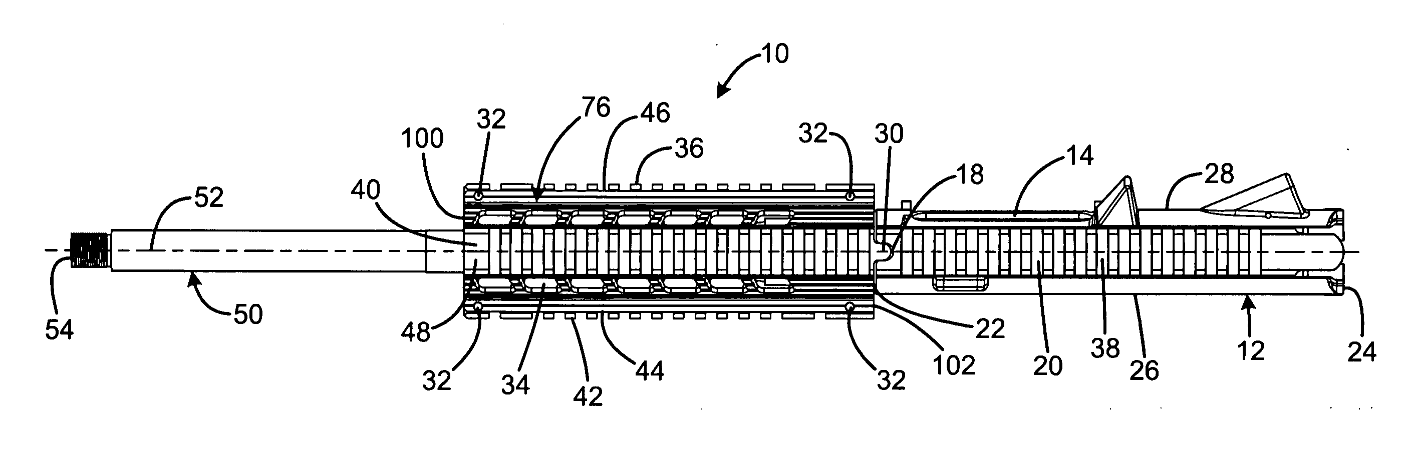
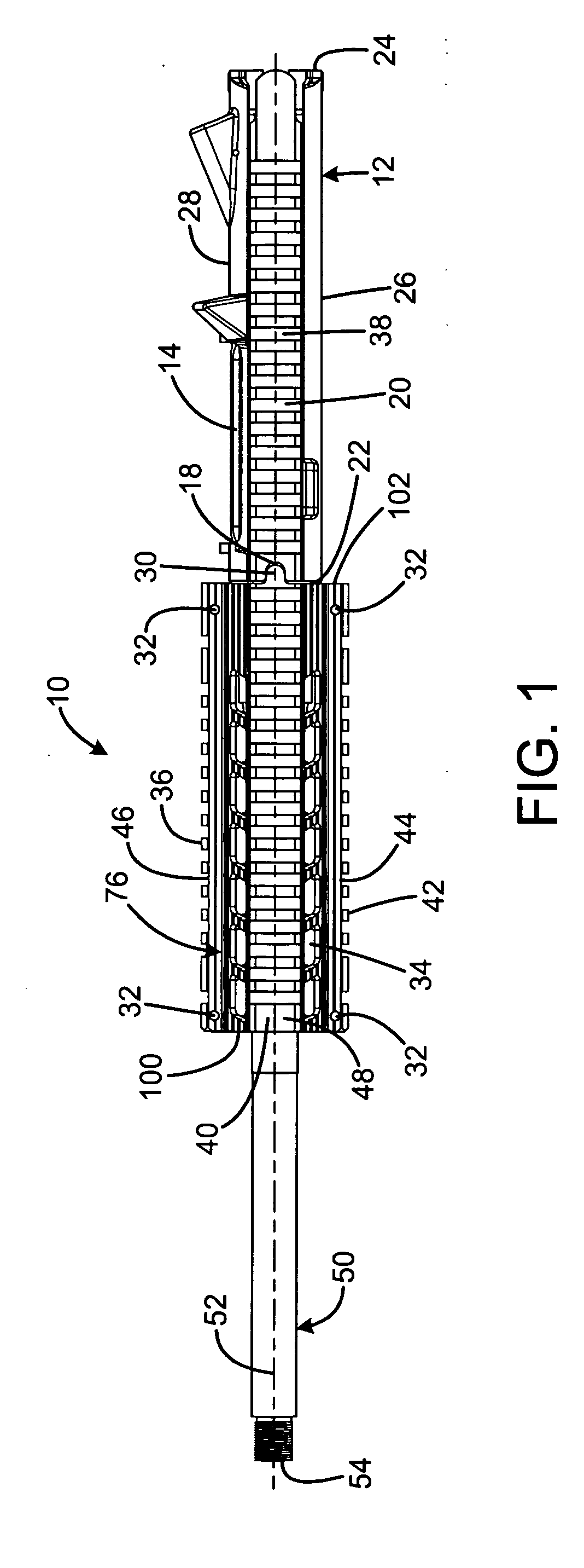
[0029]A preferred embodiment of the handguard system of the present invention is shown and generally designated by the reference numeral 10.

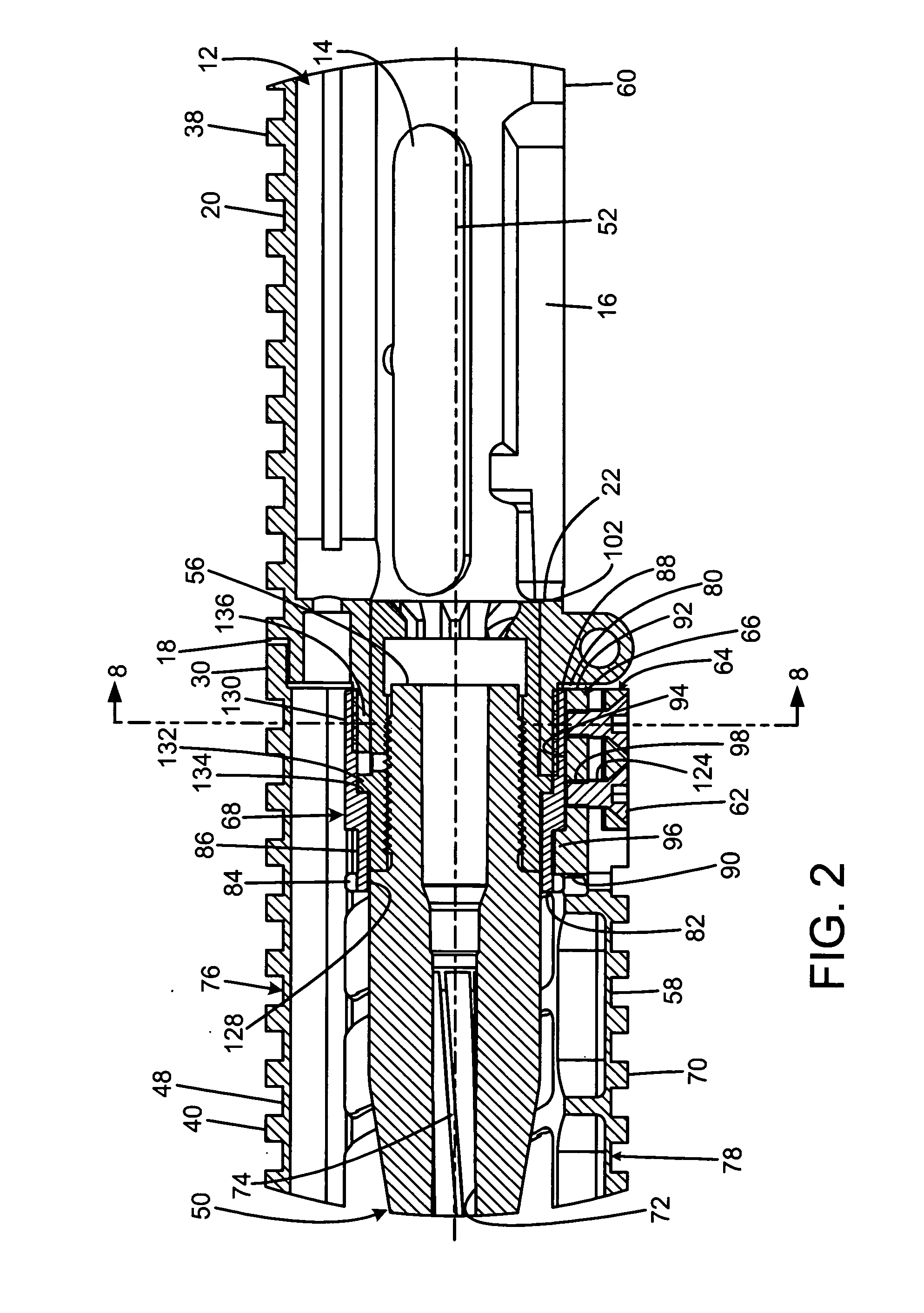
[0030]FIGS. 1 and 2 illustrate the improved handguard system 10 of the present invention installed on the upper receiver 12 and gun barrel 50 of a rifle. More particularly, the barrel has a forward muzzle end 54, a rear end 56 with a circumferential flange 132, a central bore 72 with rifling 74, and a barrel axis 52 defined by the central bore.

[0031]The upper receiver has a forward end 22, a rear end 24, a top 20, a bottom 60, a left side 26, and a right side 28. The top forms an accessory rail 38 whose forward end terminates in an alignment groove 18. Although the groove is depicted as being radiused, it can be any shape that will prevent rotational movement about the barrel axis of an element inserted therein. The right side defines an elongated aperture that forms an ejection port 14. The bottom defines a rectangular aperture that forms a mag...


PUM


Abstract

A handguard system for connecting an accessory to a firearm has a tubular body having a bore size to closely receive the body of the barrel nut. The tubular body has a tapered wedge portion that defines a gap therein. There may be a tapered clamp element adapted to fit over the wedge. The clamp element may be operable to squeeze the gap as the clamp element is pushed onto the wedge. The squeezing of the gap is operable to clamp the tubular body to the body of the barrel nut. The tubular body and the body of the barrel nut may each include a mating feature that prevents longitudinal movement of the tubular body while the mating features are engaged. The tubular body and the upper receiver may each include a mating feature that prevents rotational movement of the tubular body while the mating features are engaged.

Description

FIELD OF THE INVENTION[0001]The present invention relates to firearms, and more particularly to facilities for mounting accessories to a firearm, such as optics, laser sights, lights, and cameras.BACKGROUND OF THE INVENTION[0002]Is often desirable to mount removable accessories to a firearm. Optics and laser sights improve the user's aim; a light enables the user to illuminate his / her surroundings; a camera enables the user to create a visual record of his / her environment.[0003]Firearms have included handguards for many years to protect the user's hands from a hot barrel and to provide a secure gripping means. The four service rifles adopted by the United States armed forces during the twentieth century, the M1903, the M1 Garand, the M14, and the M16, incorporate handguards which make contact with the barrel at multiple locations. These conventional handguards, contacting the barrel in this manner, can transmit external forces to the barrel, sometimes reducing firearm accuracy.[0004...

Claims


Application Information

Patent Timeline
Patent Type & Authority Applications(United States)
IPC IPC(8): F41C27/00
CPCF41C23/16F41G11/003F41C27/00
Inventor SIROIS, CHRISTOPHER M.
Owner SCHWEIZ IND GESELLSCHAFT
Why Eureka
Try Eureka