Light-emitting device

a technology of light-emitting devices and light-emitting modules, which is applied in the direction of electric variable regulation, process and machine control, instruments, etc., can solve the problems of inability to provide a stable current for the light-emitting module, inability to precisely control the lighting property of the led by constant voltage control, and increase the manufacturing cos

Inactive Publication Date: 2011-06-02
PANELSEMI CORP
View PDF6 Cites 22 Cited by
  • Summary
  • Abstract
  • Description
  • Claims
  • Application Information

AI Technical Summary

Benefits of technology

[0014]As mentioned above, the light-emitting device according to the invention utilizes the control unit to detect the voltage of the detection terminal of the light-emitting module in response to the variations of the forward voltages of the other light-emitting modules, and utilizes the bypass unit to automatically adjust the number of the light-emitting units of the light-emitting device and to adjust the current flowing through the light-emitting unit of the light-emitting module. Thus, the variable voltage driving may be implemented.

Problems solved by technology

Thus, the manufacturing cost is increased.
Although the constant voltage control has the advantage of simpler layout design, it cannot provide a stable current for the light-emitting module.
In other words, the constant voltage control cannot precisely control the lighting property of the LED.
However, in practice, the forward voltages of the LEDs may have difference from each other because of the factors of the manufacturing process and operation temperature.
Thus, the additional power loss may occur.

Method used


Image

  • Light-emitting device
  • Light-emitting device
  • Light-emitting device

Examples


Embodiment Construction

[0022]The present invention will be apparent from the following detailed description, which proceeds with reference to the accompanying drawings, wherein the same references relate to the same elements.

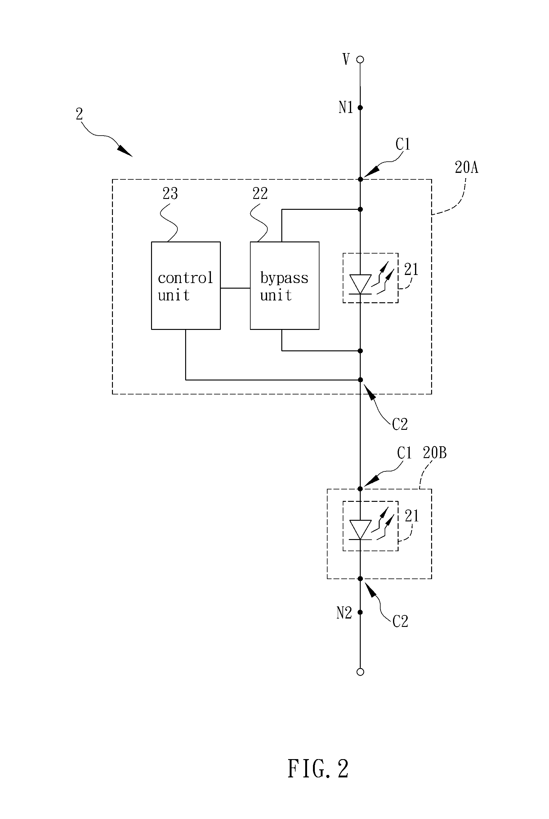
[0023]FIG. 2 is a schematic illustration showing a light-emitting device according to a preferred embodiment of the invention. Referring to FIG. 2, a light-emitting device 2 electrically connected to an external variable voltage source V includes two light-emitting modules 20A and 20B. In this embodiment, the light-emitting modules 20A and 20B are sequentially electrically connected in series between two nodes N1 and N2, which are electrically connected to the external variable voltage source V.

[0024]In practice, the external variable voltage source V may be an AC voltage or a DC voltage, and is a non-constant voltage having a level periodically or randomly varying with time. The AC voltage may be the well known mains, which means the AC power ranging from 90V to 250V, and may also be...


PUM


Abstract

A light-emitting device, electrically connected to an external variable voltage source, includes a plurality of light-emitting modules sequentially electrically connected in series and electrically connected to the external variable voltage source. Each light-emitting module has at least one light-emitting unit, a first connection terminal and a second connection terminal. At least one of the light-emitting modules has a control unit and a bypass unit electrically connected to the light-emitting unit. The second connection terminal of the light-emitting module having the bypass unit and the control unit is electrically connected to the first connection terminal of the other light-emitting module and serves as a detection terminal. The control unit detects a voltage of the detection terminal and accordingly controls the bypass unit to adjust a current flowing through the light-emitting unit.

Description

CROSS REFERENCE TO RELATED APPLICATIONS[0001]This Non-provisional application claims priority under 35 U.S.C. §119(a) on Patent Application No(s). 098141227 filed in Taiwan, Republic of China on Dec. 2, 2009, the entire contents of which are hereby incorporated by reference.BACKGROUND OF THE INVENTION[0002]1. Field of Invention[0003]The present invention relates to a light-emitting device.[0004]2. Related Art[0005]LED (light-emitting diode) is a semiconductor component and is used as the light source of indicator and outdoor media board many years ago. Compared with the traditional light source, the LED has the advantages of good efficiency, long lifetime, and strong structure, so that it has been widely used in various kinds of electronic products.[0006]The control method for the light-emitting apparatus that uses the LED as the light source commonly includes a constant voltage control and a constant current control. As shown in FIG. 1A, a conventional light-emitting apparatus 1A, ...

Claims


Application Information

Patent Timeline
Patent Type & Authority Applications(United States)
IPC IPC(8): H05B37/02H05B44/00
CPCH05B33/083H05B45/48
Inventor LIN, CHUNG-JYH
Owner PANELSEMI CORP
Why Eureka
Try Eureka