Conveyor transfer system with floating transfer platform

a technology of transfer platform and conveyor, which is applied in the direction of conveyor parts, conveyors, rollers, etc., can solve the problems of product trippage, wear or damage,

Active Publication Date: 2011-06-09
LAITRAM LLC
View PDF13 Cites 52 Cited by
  • Summary
  • Abstract
  • Description
  • Claims
  • Application Information

AI Technical Summary

Problems solved by technology

If the dead plate is vertically misaligned with one or both conveyor belts, the misalignment may provide a discontinuity that can cause products to trip.
If the dead plate is horizontally misaligned, it can come into contact with one of the belts and cause wear or damage.
Clearly, improperly aligned product-transfer plates can cause problems.

Method used


Image

  • Conveyor transfer system with floating transfer platform
  • Conveyor transfer system with floating transfer platform
  • Conveyor transfer system with floating transfer platform

Examples


Embodiment Construction

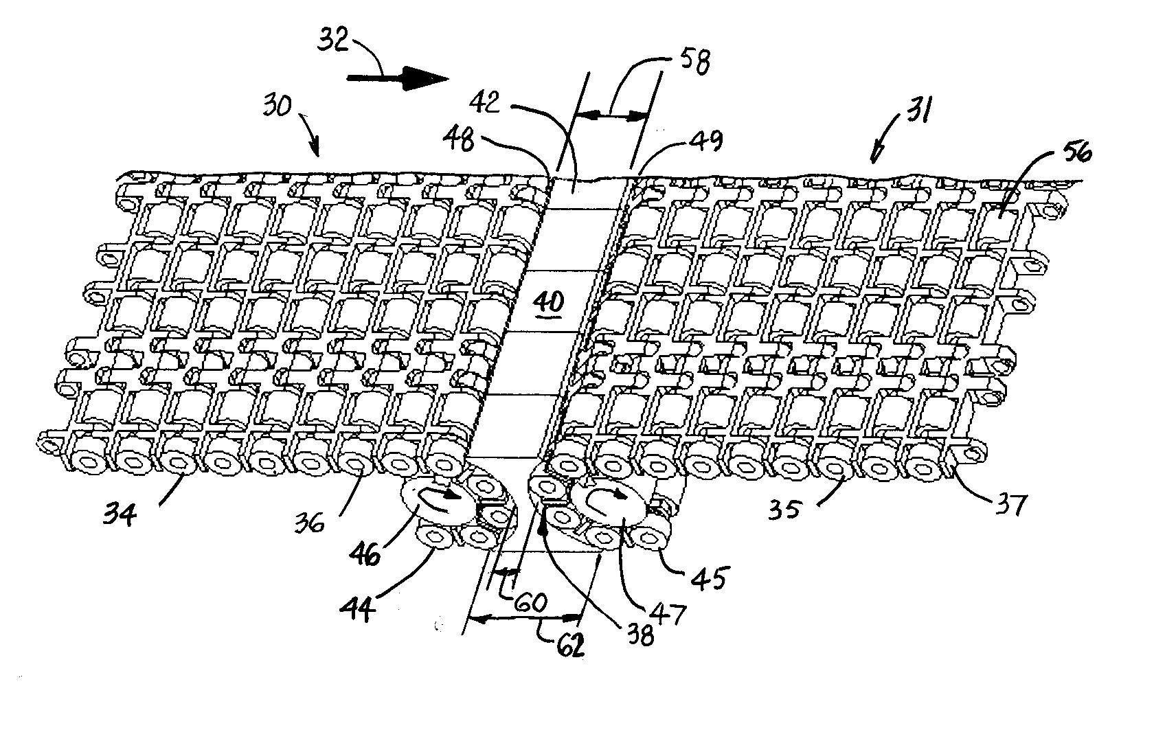
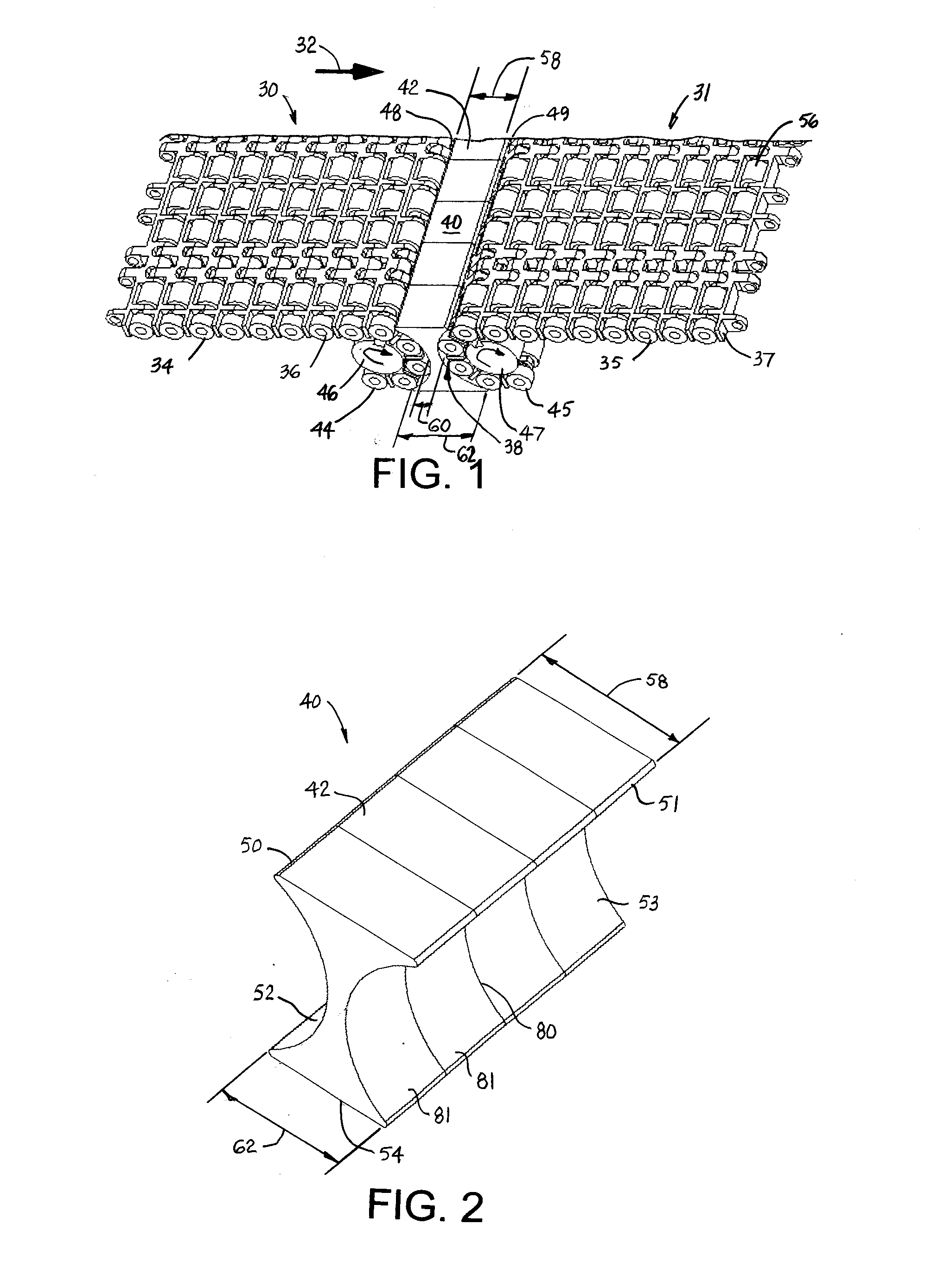
A portion of one version of a conveyor transfer system embodying features of the invention is shown in FIG. 1. The transfer system comprises an upstream conveyor 30 advancing articles in a conveying direction 32 along an upper carryway run 34 of an upstream conveyor belt 36. The upstream conveyor 30 is arranged end to end with a downstream conveyor 31 across a gap 38 largely filled with a transfer platform 40. The downstream conveyor 31 receives articles from the upstream conveyor 30 that traverse the transfer platform 40 and conveys them in the conveying direction 32 atop an upper carryway 35 of a downstream conveyor belt 37. A top transfer face 42 of the transfer platform is generally coplanar with the tops of the upstream and downstream conveyor belts for a smooth transfer. The upstream conveyor belt 36 reverses direction from the upper carryway 34 to a lower returnway 44 around a reversing element 46, such as sprockets or wheels mounted on a drive shaft at an exit end 48 of the ...


PUM


Abstract

A conveyor transfer system and a transfer platform for transferring articles from an upstream conveyor to a downstream conveyor across a gap. The transfer platform fits in the gap between two conveyors arranged end to end. At least one of the conveyors includes a conveyor belt that reverses direction around a reversing element at the gap. The transfer platform floats in the gap supported by the conveyor belt or its reversing element without a direct connection to the conveyor frame.

Description

BACKGROUNDThe transfer systems described relate generally to power-driven conveyors and more particularly to conveyors having transfer platforms over which articles travel between end-to-end conveyor belts.Belt conveyors are often arranged end-to-end with a gap between the downstream end of an upstream conveyor belt and the upstream end of a downstream conveyor belt. A dead plate is conventionally positioned in the gap to provide a ride-over surface for products transferring across the gap from the upstream conveyor belt to the downstream conveyor belt. The dead plate allows a smoother product transfer between the confronting ends of the two belts, which transition at the gap from an upper carryway run to a lower returnway run around nosebars, sprockets, or pulleys. The dead plate is conventionally affixed to the conveyor frame with its upper product-transfer surface generally coplanar with the top conveying surfaces of the upstream and downstream conveyor belts. If the dead plate i...

Claims


Application Information

Patent Timeline
Patent Type & Authority Applications(United States)
IPC IPC(8): B65G47/66B65G23/06B65G23/18B65G39/20
CPCB65G47/66B65G39/00
Inventor MARSHALL, ANGELA L.DOYLE, ROSSMCCALL, GLENN R.POINTER, ED J.RAU, BRIEN G.SCATES, DENNIS K.
Owner LAITRAM LLC
Why Eureka
Try Eureka