Controlling inductive power transfer systems

a technology of inductive power transfer and control system, which is applied in the direction of process and machine control, instruments, pulse techniques, etc., can solve the problems of system failure, loss of isup>2/sup>r losses in the primary coil, and system failure to meet the requirements of the primary uni

Active Publication Date: 2009-10-20
PHILIPS IP VENTURES BV
View PDF15 Cites 225 Cited by
  • Summary
  • Abstract
  • Description
  • Claims
  • Application Information

AI Technical Summary

Benefits of technology

[0083]Such a method can enable either or both of parasitic load and standby detection to be achieved in a robust and cost-effective manner. It is particularly advantageous in systems which may have multiple secondary devices and / or whose open magnetic nature makes it easy for parasitic objects to couple to the primary coil.

Problems solved by technology

Such systems may suffer from some problems.
A first problem is that the primary unit cannot be 100% efficient.
For example, switching losses in the electronics and I2R losses in the primary coil dissipate power even when there is no secondary device present, or when no secondary devices that are present require charge.
A second problem in such systems is that it is not possible to mechanically prevent foreign objects from being placed into proximity with the primary coil, coupling to the coil.
These eddy currents tend to act to exclude the flux, but because the material has resistance, the flowing eddy currents will suffer I2R losses which will cause heating of the object.
Such materials have high permeability, encouraging a high flux density within the material, causing large eddy currents and therefore large I2R losses.
Therefore they are not sufficient for systems such as those described in GB-A-2388716 where more than one secondary device at a time may be present.
For example, they would not work when there are two secondary devices present, one requiring charge and the other not.

Method used


Image

  • Controlling inductive power transfer systems
  • Controlling inductive power transfer systems
  • Controlling inductive power transfer systems

Examples


first embodiment

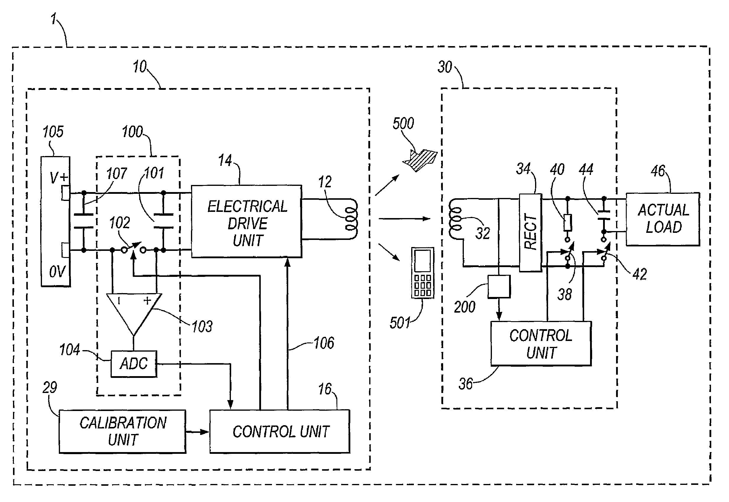
[0119]FIG. 4 shows parts of an inductive power transfer system according to the present invention. The system 1 has a primary unit 10 and a secondary device 30. FIG. 4 also shows a parasitic load 500 on the primary unit, caused for example by a foreign object placed in the vicinity of the primary unit 10. The secondary device 30 in this case is assumed to be carried in or by a host object such as a portable electrical or electronic device. As explained hereinbefore the secondary device 30 and / or host object also inevitably impose a “friendly” parasitic load 501 on the primary unit 10.

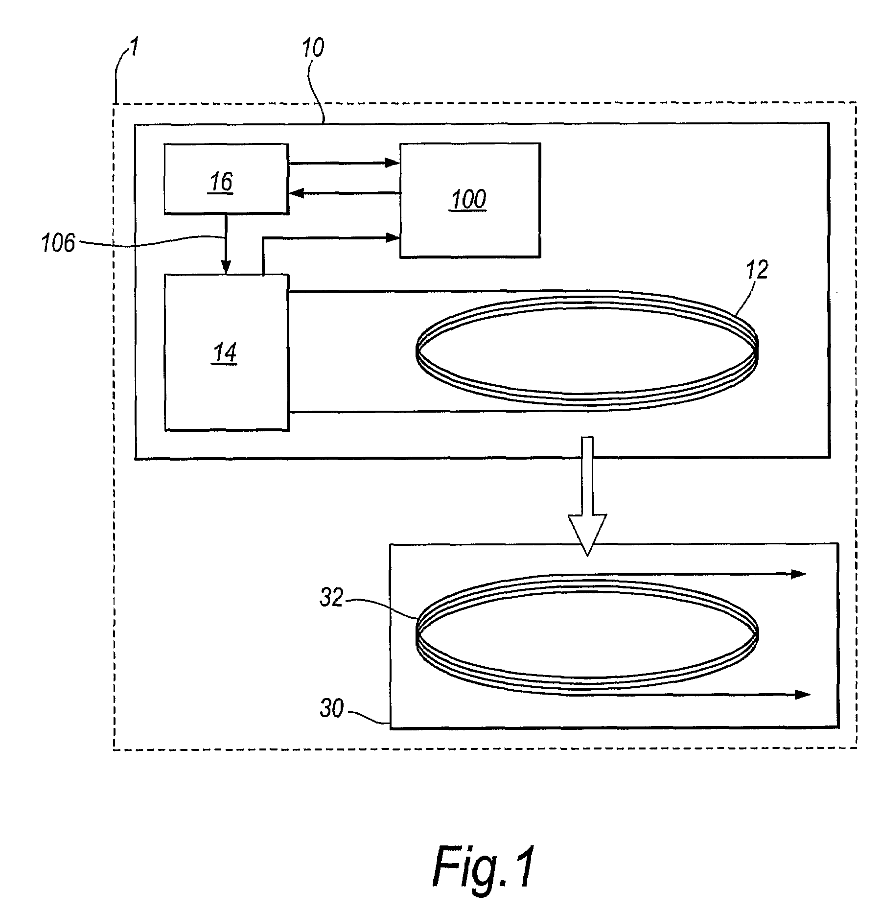
[0120]As described earlier with reference to FIG. 1, the primary unit 10 comprises a primary coil 12, an electrical drive unit 14, a control unit 16 and a power measurement unit 100. The electrical drive unit 14 has an input connected to an output of the control unit 16 supplying the AC voltage signal 106. The output nodes of the electrical drive unit 14 are connected to the primary coil 12.The electric...

third embodiment

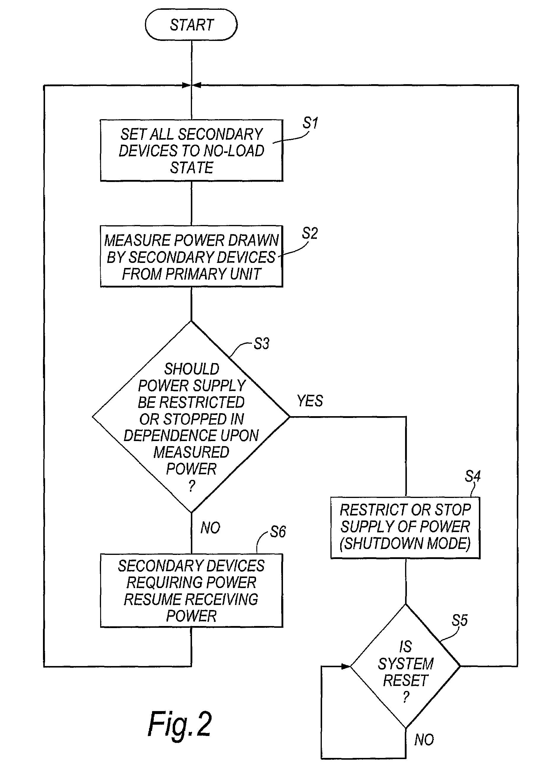
[0197]FIG. 12 shows parts of a power transfer system according to the present invention. This system implements the shutdown detection method of FIG. 11 using an RFID communication method.

[0198]The FIG. 12 system comprises a plurality of secondary devices 6001, 6002, . . . , 600n. The system of FIG. 12 also comprises a primary unit 700. The primary unit 700 comprises an RFID unit 710, a control unit 720 and a power measurement unit 730. The control unit 720 corresponds generally to the control unit 16 described previously with reference to FIG. 1, and the power measurement unit 730 corresponds generally to the power measurement unit 100 described in reference to FIG. 1.

[0199]The features of the secondary device 600 are generally the same as those of the secondary device 30 in FIG. 4 except that the elements 38, 40, 42, 44 and 200 may be omitted. Instead of these elements, each secondary device 600 comprises its own load measuring unit 610 and an RFID unit 620. The load measuring uni...


PUM


Abstract

An inductive power transfer system (1) comprises a primary unit (10) operable to generate an electromagnetic field and at least one secondary device (30), separable from the primary unit, and adapted to couple with the field when the secondary device is in proximity to the primary unit so that power can be received inductively by the secondary device from the primary unit without direct electrical conductive contacts therebetween. The system detects if there is a substantial difference between, on the one hand, a power drawn from the primary unit and, on the other hand, a power required by the secondary device or, if there is more than one secondary device, a combined power required by the secondary devices. Following such detection, the system restricts or stops the inductive power supply from the primary unit. Such a system can detect the presence of unwanted parasitic loads in the vicinity of the primary unit reliably.

Description

BACKGROUND OF THE INVENTION[0001]The present invention relates to controlling inductive power transfer systems for use, for example, to power portable electrical or electronic devices.[0002]This application claims priority from the applicant's copending applications GB 0410503.7 filed on 11 May 2004 and GB 0502775.0 filed on 10 Feb. 2005, the entire content of each of which is incorporated herein by reference.[0003]Inductive power transfer systems suitable for powering portable devices may consist of two parts:[0004]A primary unit having at least one primary coil, through which it drives an alternating current, creating a time-varying magnetic flux.[0005]A secondary device, separable from the primary unit, containing a secondary coil. When the secondary coil is placed in proximity to the time-varying flux created by the primary coil, the varying flux induces an alternating current in the secondary coil, and thus power may be transferred inductively from the primary unit to the secon...

Claims


Application Information

Patent Timeline
Patent Type & Authority Patents(United States)
IPC IPC(8): H02J3/00H02J17/00
CPCH02J5/005H01F38/14G05F1/66H02J17/00H02J50/12H02J50/80H02J50/60H02J50/10H02J50/40G05F1/30H02H1/0069H02M7/217H02M7/538
Inventor STEVENS, MICHAEL CRAIGKNILL, ALEXANDER CHARLESDUNTON, JOHN ROBERTDAMES, ANDREW NICOLASLAMB, KEVIN ALAN
Owner PHILIPS IP VENTURES BV
Why Eureka
Try Eureka