Unified user login for co-location facilities

a co-location facility and user login technology, applied in the field of co-location facilities, can solve the problems of unnecessary overhead and cost for global companies and their customers

Active Publication Date: 2011-06-16
EQUINIX
View PDF39 Cites 20 Cited by
  • Summary
  • Abstract
  • Description
  • Claims
  • Application Information

AI Technical Summary

Benefits of technology

[0005]For some embodiments, a central relational database is used to contain a set of tables and schema to associate individual agreements with different levels of access rights and user permissions associated with different users associated with the same customer. An asset hierarchical model is configured to enable grouping of the assets in one or more asset groups, and a user group model is configured to enable grouping of the users of the customer in one or more user groups and according to geographically distinct co-location facilities. A logical customer organization model is applied to group the individual agreements into separate logical customer organizations, wherein the groupings can be region based groupings, organization groupings and departmental groupings. Unified login identification (ID) model is applied to enable a first user to login to an Internet portal using a first login ID to access a first asset in a first asset group according to a first logical customer organization, and using a same first login ID to access a second asset in the first asset group according to the first logical customer organization. The unified login ID model also enable the first user to login to the portal using a second login ID to access one or more assets in a second asset group according to a second logical customer organization. The central relational database and the portal are hosted on one or more servers connected to the Internet.

Problems solved by technology

As the number of customer increases and / or the number of agreements per customer increases, the same approach can cause unnecessary overheads and costs for the global companies as well as for their customers.

Method used


Image

  • Unified user login for co-location facilities
  • Unified user login for co-location facilities
  • Unified user login for co-location facilities

Examples


Embodiment Construction

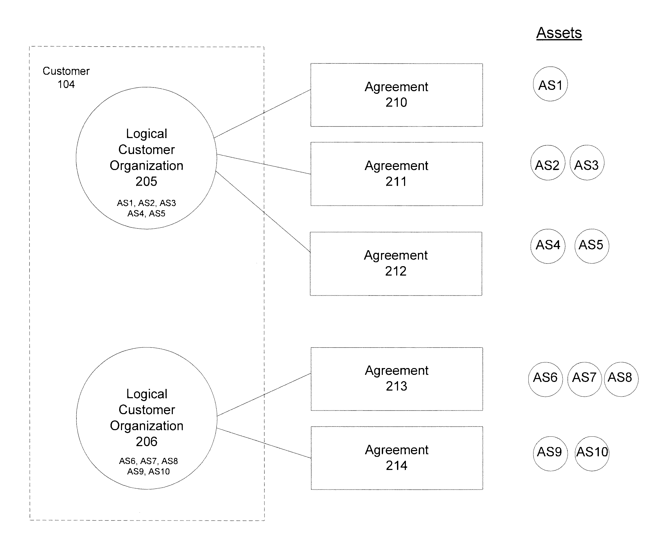
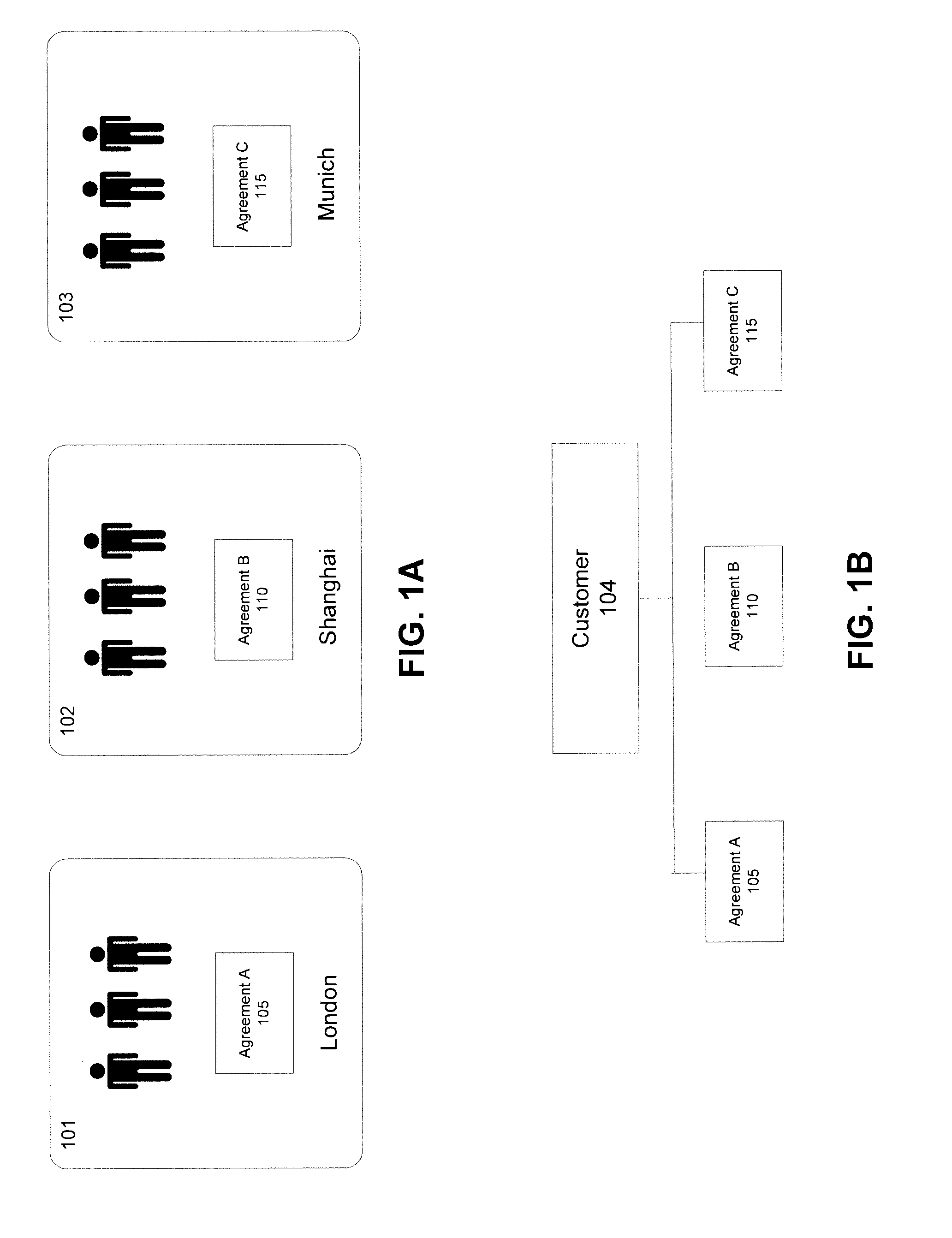
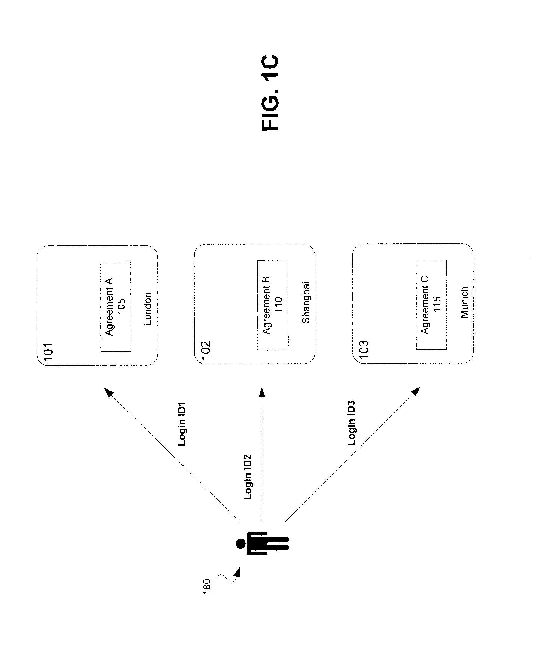
[0024]For some embodiments, methods and systems are described to enable a service provider to more efficiently offer its services to customers. The service provider may have multiple agreements with a customer, and each of the agreements may be associated with one or more assets of the service provider. The assets may be geographically specific. The methods and systems may enable users of the customers to access the assets using unified user logins. This is advantageous over the traditional approach where a different user login is assigned to the same user for each of the assets. The methods and systems extend user management capabilities to include asset based permission management. User groups, asset groups, asset trees and asset permissions may be defined. A central relational database containing a set of tables and schema may be used to store information relating to the user groups, asset groups, asset trees and asset permissions.

[0025]For some embodiments, the methods and syste...


PUM


Abstract

A logical customer organization model is applied to group the individual agreements into separate logical customer organizations, wherein the groupings can be region based groupings, organization groupings and departmental groupings. Unified login identification (ID) model is applied to enable a first user to login to a portal using a first login ID to access a first asset in a first asset group according to a first logical customer organization. The unified login ID model enables the first user to use the same first login ID to access a second asset in the first asset group according to the first logical customer organization. The unified login ID model also enables the first user to login to the portal using a second login ID to access one or more assets in a second asset group according to a second logical customer organization. Each of the first and second logical customer organization may be associated with one or more asset groups and one or more user groups.

Description

RELATED APPLICATIONS[0001]This application claims the benefit of and priority to U.S. Provisional Application titled “An Ethernet Exchange” filed on Dec. 10, 2009 having application Ser. No. 61 / 285,371 and U.S. Provisional Application titled “An Improved Ethernet Exchange” filed on Apr. 12, 2010 having application Ser. No. 61 / 323,066, both are incorporated by reference herein.NOTICE OF COPYRIGHT[0002]A portion of the disclosure of this patent document contains material that is subject to copyright protection. The copyright owner has no objection to the facsimile reproduction by anyone of the software engine and its modules, as it appears in the Patent and Trademark Office Patent file or records, but otherwise reserves all copyright rights whatsoever.FIELD OF THE INVENTION[0003]Embodiments of the invention generally relate to co-location facility. More particularly, an aspect of an embodiment of the invention relates to unified user login for global customers with multiple agreements...

Claims


Application Information

Patent Timeline
Patent Type & Authority Applications(United States)
IPC IPC(8): H04L9/32
CPCG06Q10/06G06F21/604H04L41/28H04L41/5006H04L67/535G06F11/3089G06F11/3438H04L41/0893
Inventor LILLIE, BRIAN JAMESJEYAPAUL, JAGANATHANDORAISWAMY, VIJAAYWENG, TSUNYENJANKEN, NATHANNAVARATNA, MOHAN
Owner EQUINIX
Why Eureka
Try Eureka