

Pneumatic tire
- Summary
- Abstract
- Description
- Claims
- Application Information
AI Technical Summary
Benefits of technology
Problems solved by technology
Method used
Image

Examples
first embodiment
Structure of Tread Pattern
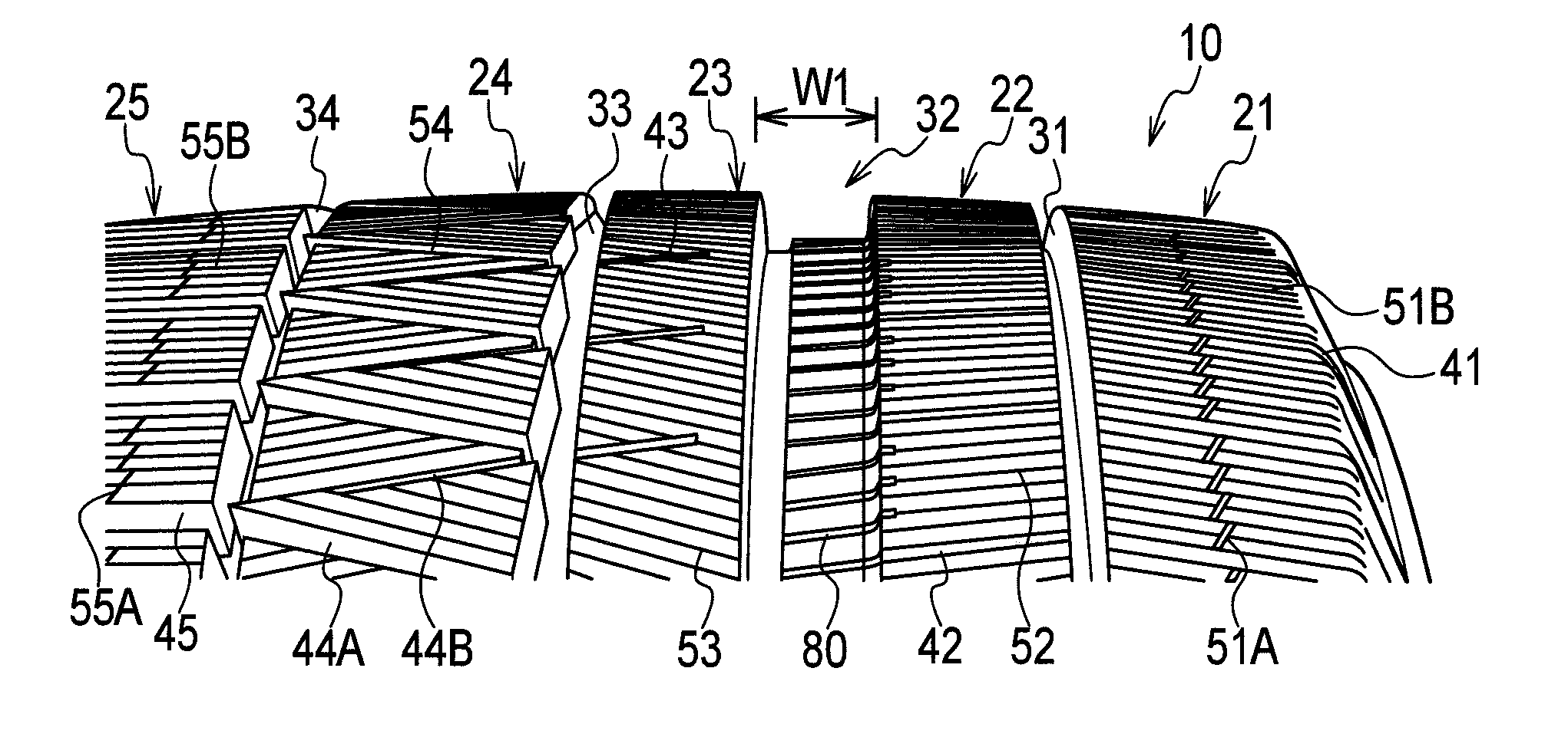
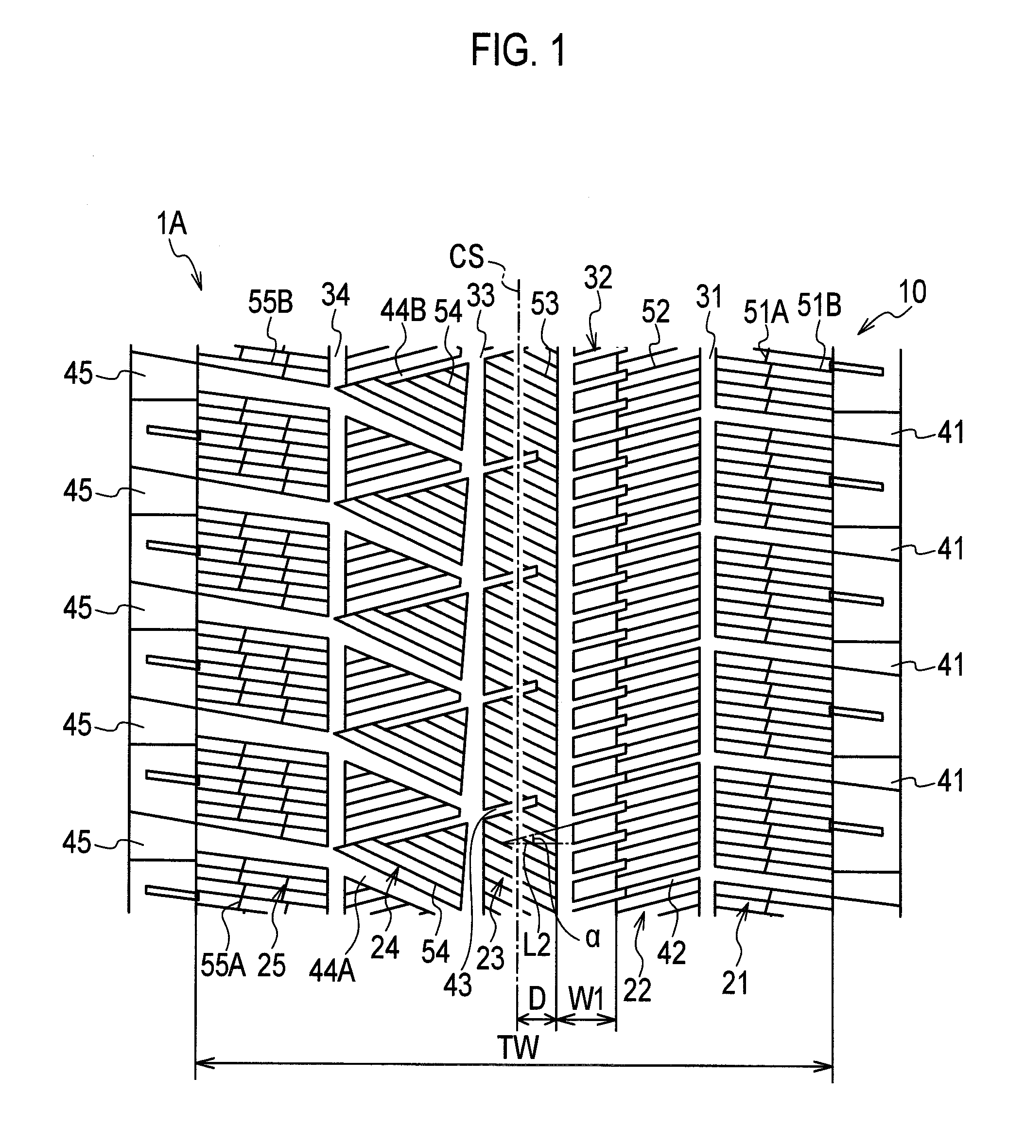
[0036]In the following, the structure of a tread pattern of a pneumatic tire 1A according to a first embodiment will be described by referring to the drawings. FIG. 1 is a developed view showing the tread pattern of the pneumatic tire 1A according to the first embodiment. FIG. 2 is an enlarged view showing a part of the pneumatic tire 1A according to the first embodiment.
[0037]The pneumatic tire 1A according to the first embodiment is a common radial tire including bead parts, a carcass layer, and a belt layer (not illustrated). Moreover, the pneumatic tire 1A according to the first embodiment has a pattern which is asymmetrical about the tire's equatorial plane CS.
[0038]As shown in FIGS. 1 and 2, the pneumatic tire 1A includes a tread surface 10 that comes into contact with the road surface, i.e., a land portion 20 that forms the surface of the tread part. By the land portion 20, formed are: multiple circumferential grooves 30 extending in the tire circumf...
second embodiment
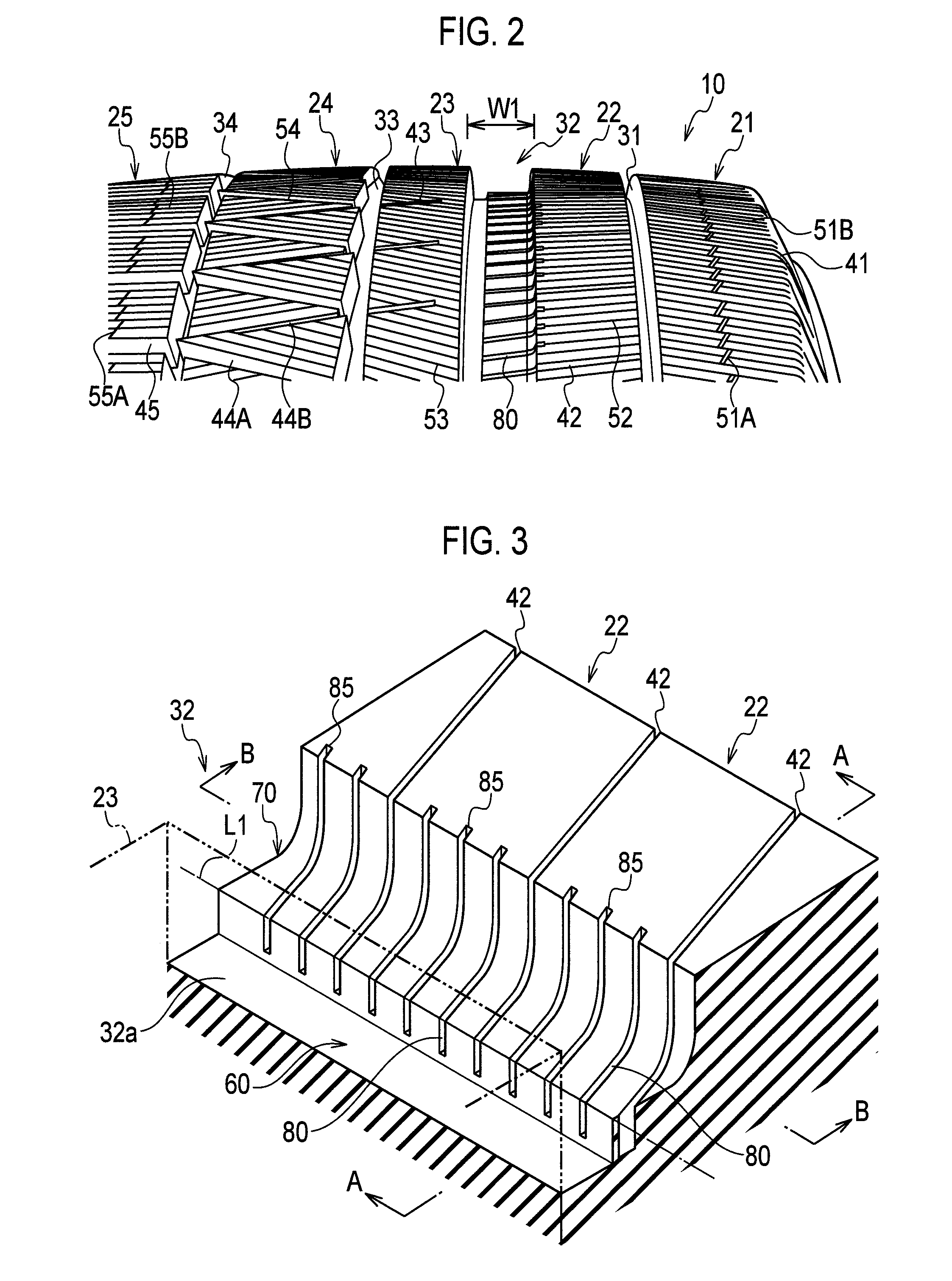
[0071]In the following, the structure of a tread pattern of a pneumatic tire 1B according to a second embodiment will be described by referring to FIGS. 8 to 10. FIG. 8 is a developed view showing the tread pattern of the pneumatic tire 1B according to the second embodiment. FIG. 9 is an enlarged view showing a part of the pneumatic tire 1B according to the second embodiment. In FIG. 9, the sipes 50 are omitted. FIG. 10 is a perspective view showing a part of a circumferential groove 32 according to the second embodiment. Note that the same portions as those of the pneumatic tire 1A according to the above first embodiment will be denoted by the same reference numerals, and differences therebetween will be mainly described.
[0072]As shown in FIGS. 8 and 9, in a land portion 22 located at the tread shoulder side of the circumferential groove 32, one end portion of each lug groove 42 is opened to the circumferential groove 31 whereas the other end portion of the lug groove 42 ends insid...
PUM
 Abstract
Description
Claims
Application Information