Automatic spring forming equipment

A spring forming and equipment technology, applied in the field of spring processing and manufacturing, can solve the problems of affecting spring forming efficiency and easy slipping, and achieve the effects of preventing vibration, improving forming efficiency, and improving clamping effect

Inactive Publication Date: 2022-04-26
苏州旭达精密五金有限公司
View PDF0 Cites 0 Cited by
  • Summary
  • Abstract
  • Description
  • Claims
  • Application Information

AI Technical Summary

Problems solved by technology

[0005] Aiming at the deficiencies of the prior art, the present invention provides automatic spring forming equipment, which has the advantages of preventing slippage during steel wire transmission, improving spring forming efficiency, and preventing vibration during steel wire transmission, etc., and solves the problem of the existing equipment that is easy to slip during steel wire transmission and frequently overhauled The problem of spring forming efficiency

Method used


Image

  • Automatic spring forming equipment
  • Automatic spring forming equipment
  • Automatic spring forming equipment

Examples


Embodiment Construction

[0030] The following will clearly and completely describe the technical solutions in the embodiments of the present invention with reference to the accompanying drawings in the embodiments of the present invention. Obviously, the described embodiments are only some, not all, embodiments of the present invention. Based on the embodiments of the present invention, all other embodiments obtained by persons of ordinary skill in the art without making creative efforts belong to the protection scope of the present invention.

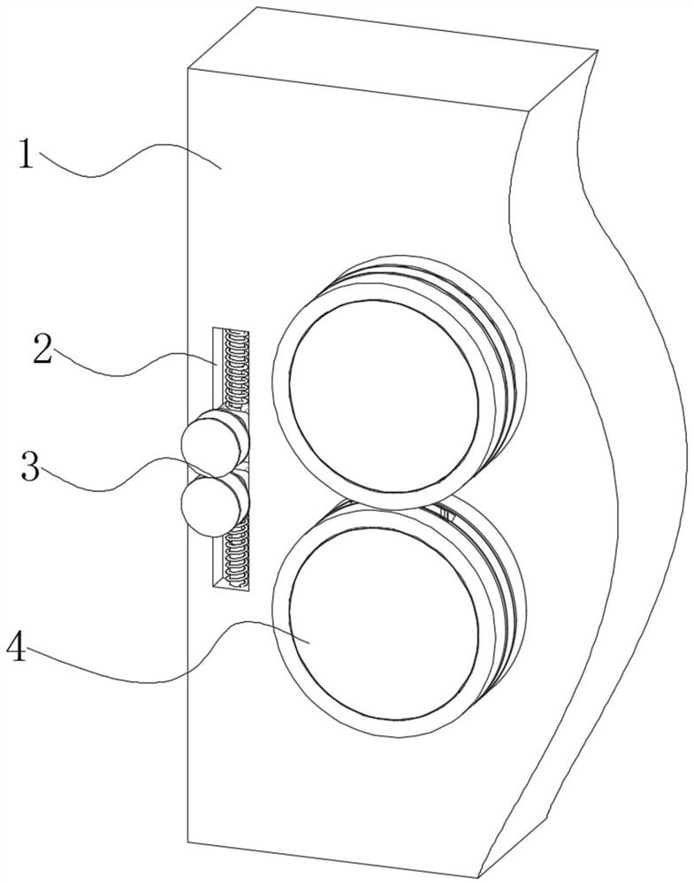
[0031] see figure 1 , automatic spring forming equipment, including a body 1, a card slot 2 is opened on the left side of the front of the body 1, an anti-shake mechanism 3 is movably connected to the inside of the card slot 2, a fastening mechanism 4 is provided on the front of the body 1, and its center point and the center point of the anti-shake mechanism 3 are located on the same horizontal plane.

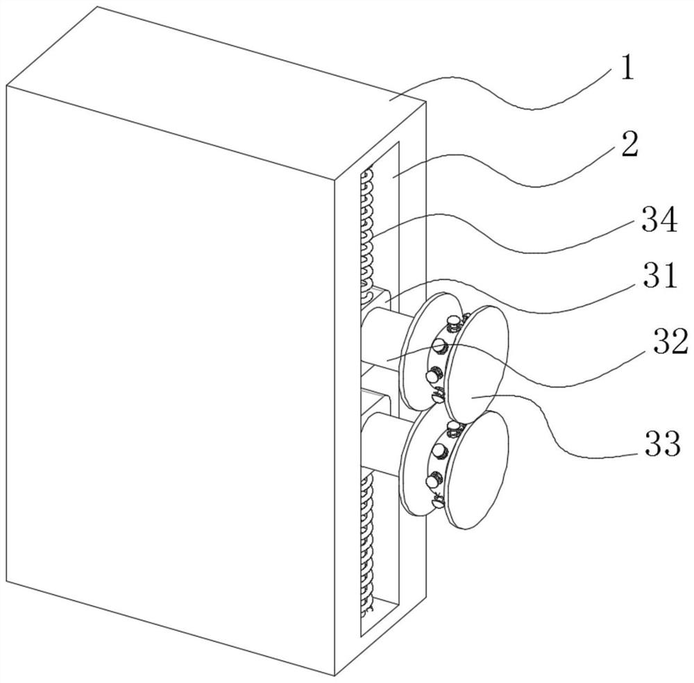
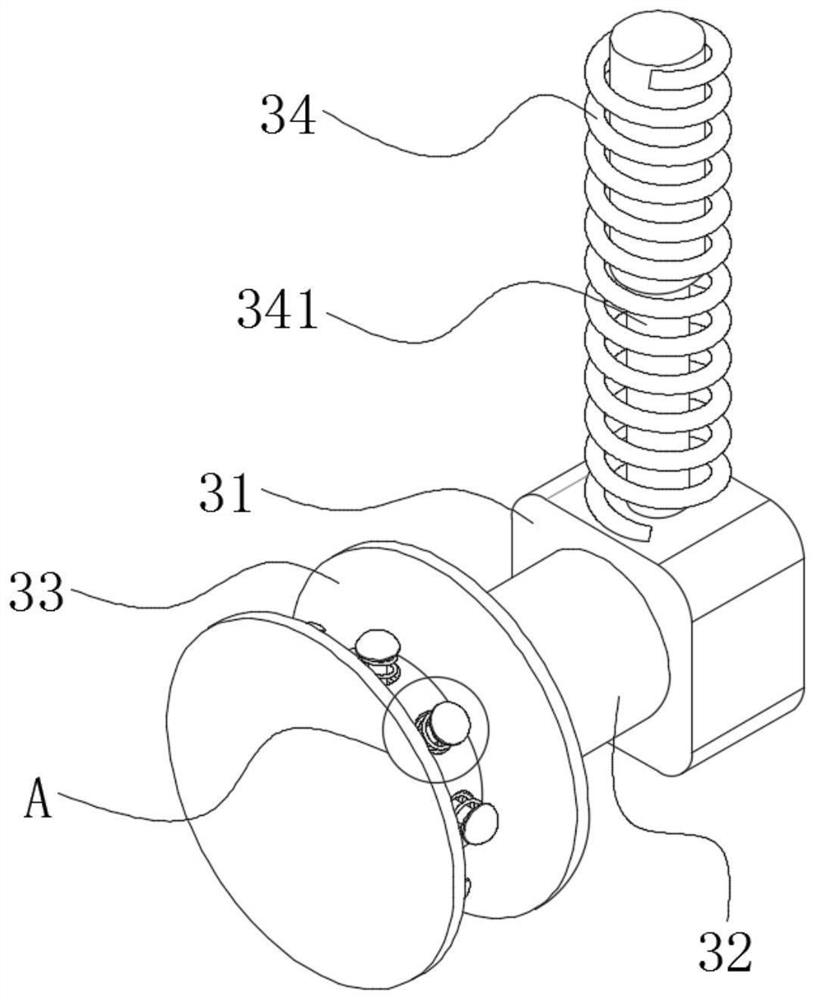
[0032] see Figure 2-4 The anti-shake mechanism 3 incl...


PUM


Abstract

The invention relates to the technical field of spring machining and manufacturing, and discloses automatic spring forming equipment which comprises a machine body, a clamping groove is formed in the left side of the front face of the machine body, an anti-shake mechanism is movably connected into the clamping groove, a fastening mechanism is arranged on the front face of the machine body, and the center point of the fastening mechanism and the center point of the anti-shake mechanism are located on the same horizontal plane. An outer sliding ring is rotationally connected to the outer side of the fixing block, and a rubber pad is arranged on one side of the top of the front face of the outer sliding ring. When an outer sliding ring rotates to drive a connecting plate to rotate to one side of the bottom of a fixed block through a top plate, the connecting plate slides along one side of an inclined surface of an inclined top block, so that the height of the top plate can be slowly increased through the connecting plate, rubber pads can be upwards jacked up, and a penetrating steel wire can be clamped through the two groups of rubber pads; meanwhile, the friction force of contact between the steel wire and the rubber pad can be improved through the friction block, so that the clamping effect on the steel wire can be further improved, and the steel wire can be prevented from being damaged by rigid contact through the rubber pad.

Description

technical field [0001] The invention relates to the technical field of spring processing and manufacturing, in particular to automatic spring forming equipment. Background technique [0002] With the continuous progress of the times, the development of science and technology has become more and more developed, but springs are indispensable and important components no matter in the past or in the future development. Usually, springs are often used in industries, ranging from aircraft and warships to Springs are used in various products such as mobile phones and cameras. With the advancement of technology, the equipment and technology for making springs have become more mature, and the types of springs produced are also diverse. [0003] The current spring forming equipment generally straightens the steel wire coils used for making springs first, then straightens the straightened steel wires, and then sends the steel wires to the diameter-changing mechanism and pitch-changing ...

Claims


Application Information

Patent Timeline
Patent Type & Authority Applications(China)
IPC IPC(8): B21F3/04
CPCB21F3/04
Inventor 郑贤淼叶鸿君
Owner 苏州旭达精密五金有限公司
Why Eureka
Try Eureka