Leftward and rightward double-bending type numerical-controlled pipe bending machine

A pipe bending machine and pipe bending technology, applied in metal processing equipment, feeding devices, positioning devices, etc., can solve problems affecting the quality of pipe bending, unstable pipe bending devices, and inability to configure swing arm clamping mechanisms, etc., to achieve Improve the quality, improve the efficiency of pipe bending, and ensure the effect of power consistency

Active Publication Date: 2017-10-24
浙江和良智能装备有限公司
View PDF17 Cites 28 Cited by
  • Summary
  • Abstract
  • Description
  • Claims
  • Application Information

AI Technical Summary

Problems solved by technology

Although it can achieve left and right co-bending, in order to avoid the interference of the rotary gear on the bending process, the two centering shafts are required to be far away from the rotary gear in height, and the swing arm and the clamping mold on the swing arm cannot be configured. Mechanism, it is easy to cause the instability of the whole pipe bending device and affect the quality of the pipe bending

Method used


Image

  • Leftward and rightward double-bending type numerical-controlled pipe bending machine
  • Leftward and rightward double-bending type numerical-controlled pipe bending machine
  • Leftward and rightward double-bending type numerical-controlled pipe bending machine

Examples


Embodiment 1

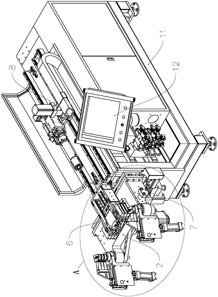
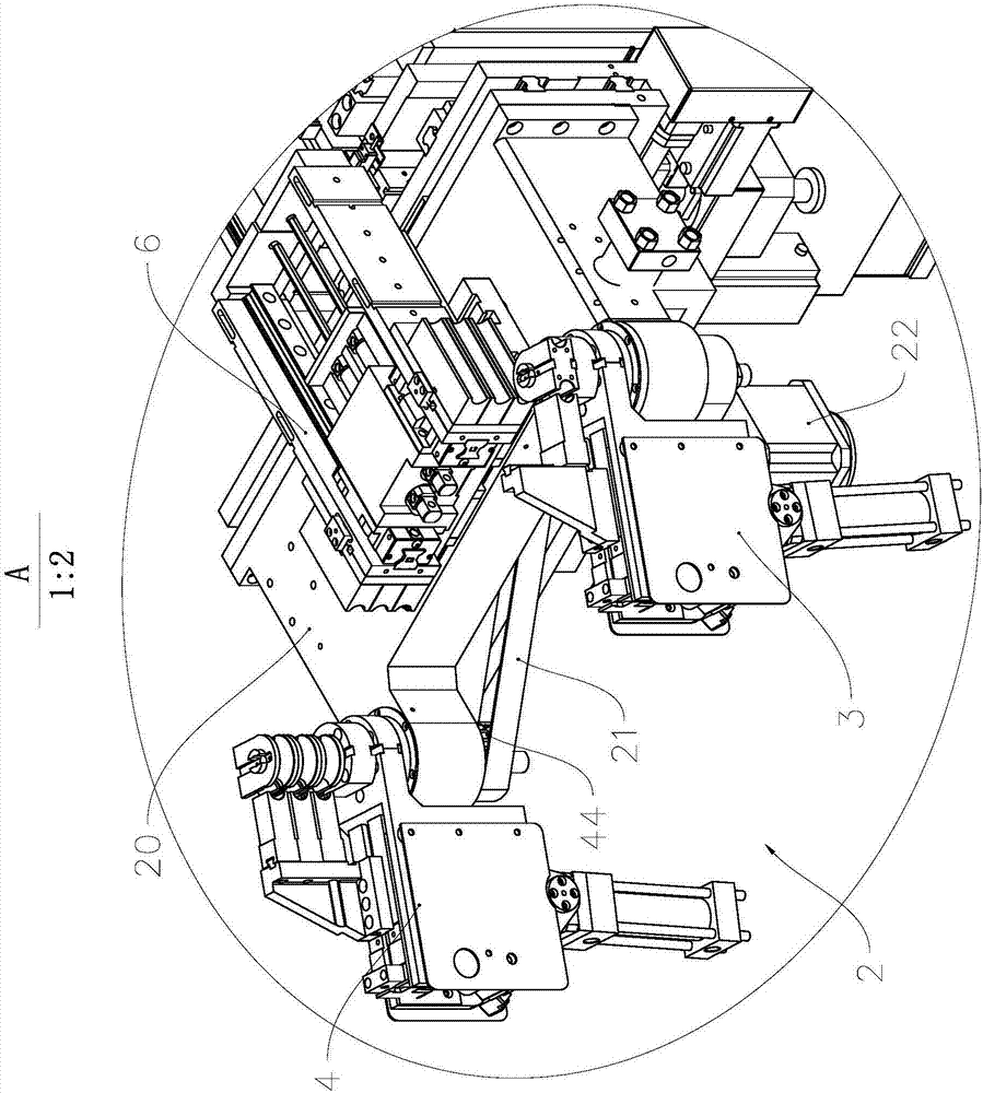
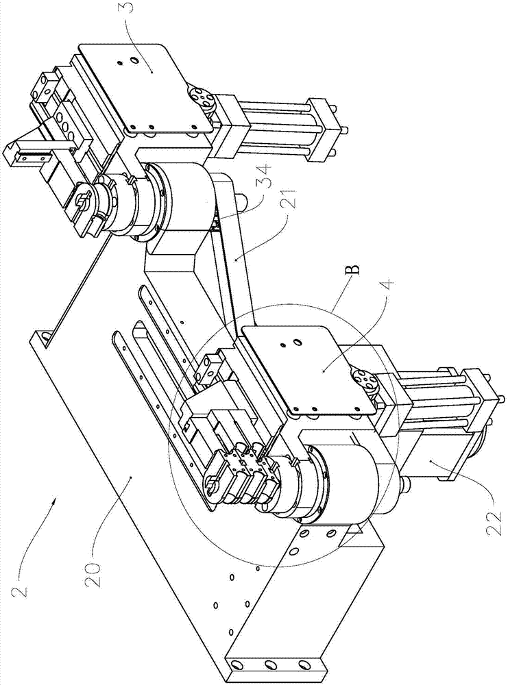
[0031] see figure 1 and figure 2 , the CNC pipe bending machine 1 includes a frame 11, a control unit, and a pipe bending device and a feeding trolley 8 that are installed on the frame 11 and controlled by the control unit; wherein, the pipe bending device includes a machine head 2 and a mold guide unit 6 And die changing unit 7. In the following description of the specific structure, the pipe fitting to be bent is a pipe fitting clamped on the feeding spindle of the feeding trolley 8. In this embodiment, since the feeding spindle is arranged along the horizontal direction, the axial direction of the pipe fitting to be bent is Arranged horizontally.

[0032] In this embodiment, the control unit includes a processor, a memory, and a touch control panel 12. The processor receives input instructions from the operator through the touch control panel 12, and simultaneously controls the pipe bending device and the material feeding by executing a computer program stored in the mem...

Embodiment 2

[0062]As a description of Embodiment 2 of the present invention, only the differences from Embodiment 1 above will be described below, that is, only the structure of the clamping mold assembly will be described.

[0063] see Figure 9 and Figure 10 , clamping mold assembly 9 comprises clamping mold base 93, the clamping mold (not shown) that is installed on the mounting surface 930 of clamping mold base 93, the clamping mold adjusting screw 920 that is rotatably installed on the swing arm 92, And be located at the clamping mold driving mechanism between swing arm 92 and clamping mold seat 93. The mold clamping drive mechanism includes a booster rocker 941 , a booster link 942 , a lever 943 and an actuator 95 .

[0064] Actuator 95 is an oil cylinder, and its oil cylinder rod 951 constitutes the mover of actuator 95, and cylinder body 952 constitutes the stator of actuator 95, and cylinder body 952 is hinged on the swing arm 92 by hinge shaft 953, and lever 943 is the booste...

Embodiment 3

[0072] As an explanation of Embodiment 3 of the present invention, only the differences from Embodiment 2 above will be described below.

[0073] see Figure 12 , by hinged more than one guide swing rod 964 on the mounting base to replace the arc-shaped chute in the above-mentioned embodiment 2, that is, hinged to the swing arm through the hinge shaft 965, and the swing end of the guide swing rod 964 passes through the hinge shaft 966 and Clamping base 96 is hinged, guides fork 964 and lever 963 and maintains parallel arrangement in swing process, and the resistance arm equal length of its length and lever 963. That is, the swing track of the swing end of the guiding swing rod 964 constitutes an arc-shaped guide rail for the movement of the mold clamping base 96 relative to the mounting base.

[0074] In order to make the guide swing link 964 form a substantially planar swing surface when swinging, to improve the stability of the clamping mold driving, it can be realized by a...


PUM


Abstract

The invention relates to a leftward and rightward double-bending type numerical-controlled pipe bending machine, and belongs to the technical field of pipe processing. The leftward and rightward double-bending type numerical-controlled pipe bending machine comprises a rack, a control unit, a pipe bending device and a feeding vehicle which are mounted on the rack and controlled by the control unit, wherein the pipe bending device comprises a machine head, a die guide unit and a die changing unit; the machine head comprises a mounting seat, a leftward pipe bending unit and a rightward pipe bending unit which are mounted on the mounting seat and driven by a same pipe bending motor; each of the leftward and rightward pipe bending units comprises a circular die, a swing arm and a clamping die mounted on the swing arm; the die changing unit is controlled by the control unit to drive the machine head to move in transverse and vertical directions being perpendicular to the axial direction of a pipe to be bent relative to the rack, so that the numerical-controlled pipe bending machine can switch between a leftward bending working mode and a rightward bending working mode. According to the leftward and rightward double-bending type numerical-controlled pipe bending machine, the same pipe bending motor drives the leftward pipe bending unit and the rightward pipe bending unit simultaneously, at the same time the switching between the leftward pipe bending unit and the rightward pipe bending unit is realized through the die changing unit, not only is the pipe bending quality effectively improved, but also the compactness of the integrated layout is improved, and therefore the leftward and rightward double-bending type numerical-controlled pipe bending machine can be extensively applied to fields such as air conditioning and aviation.

Description

technical field [0001] The invention relates to pipe material processing equipment, in particular to a left and right co-bending numerical control pipe bending machine. Background technique [0002] CNC pipe bending machines are widely used in air conditioners, automobiles, ships, aerospace and other industrial fields. A circular die for controlling the radius of the pipe bend, a swing arm and a clamping die installed on the swing arm for clamping pipe fittings together with the circular die are installed on the top. According to the different bending directions, it can be divided into left-bend type pipe bender, right-bend type pipe bender and left-right bend type pipe bender. [0003] The patent document with the publication number CN101817038A discloses a bending mechanism for building a left and right co-bending CNC pipe bender, including a support, a rotary gear rotatably installed on the support, and a rotary gear for driving the rotary gear. The motor is slidably in...

Claims


Application Information

Patent Timeline
Patent Type & Authority Applications(China)
IPC IPC(8): B21D7/12B21D7/024B21D7/16B21D43/10
CPCB21D7/024B21D7/12B21D7/16B21D43/006B21D43/105
Inventor 斯文尼尔·帕特里克·路易斯·雅克赵俊强李良有蔡前龙
Owner 浙江和良智能装备有限公司
Why Eureka
Try Eureka