
Flexible thermoelectric generator, wireless sensor node including the same and method of manufacturing the same

a technology of thermoelectric generators and wireless sensors, applied in the manufacture/treatment of thermoelectric devices, instruments, heat measurement, etc., can solve the problems of inability to provide voltages that meet input requirements, disadvantages in size and performance, and limited efficiency and electric potential of existing thermoelectric generators

Inactive Publication Date: 2011-06-23
ELECTRONICS & TELECOMM RES INST
View PDF3 Cites 43 Cited by
  • Summary
  • Abstract
  • Description
  • Claims
  • Application Information

AI Technical Summary

Benefits of technology

[0013]The present invention is directed to a self-driven wireless sensor node operated by an energy storage device in which energy is ch...

Problems solved by technology

However, the existing thermoelectric generator has a limited efficiency and electric potential when it is formed in a relatively small size.
Since a conventional semiconductor deposition technique is used to manufacture the thermoelectric generator, the thermoelectric generators formed through difficult synthesis processes are subjected to numerous restrictions in process, which lead to disadvantages in size and performance.
These thermoelectric generators cannot provide voltages satisfying input requirements of numerous devices including power control electrons.
However, the wireless sensor node energized by a battery has a disadvantage in power due to a limited lifespan of the battery.
Therefore, remote apparatus exclusively dependent on the batteries are essentially restricted by the lifespan and reliability of the batteries.
However, since the conventional power solution is inappropriate or too expensive, it is impossible to realize this solution.
That is, power feed to all sensors by batteries requires much cost due to initial installation and periodical movement, and causes performance restriction of the batteries.
However, this method is also impractical due to a complex circuit and excessive cost.

Method used


Image

  • Flexible thermoelectric generator, wireless sensor node including the same and method of manufacturing the same
  • Flexible thermoelectric generator, wireless sensor node including the same and method of manufacturing the same
  • Flexible thermoelectric generator, wireless sensor node including the same and method of manufacturing the same

Examples


Embodiment Construction

[0026]The present invention will be described more fully hereinafter with reference to the accompanying drawings, in which exemplary embodiments of the invention are shown. This invention may, however, be embodied in different forms and should not be construed as limited to the embodiments set forth herein.

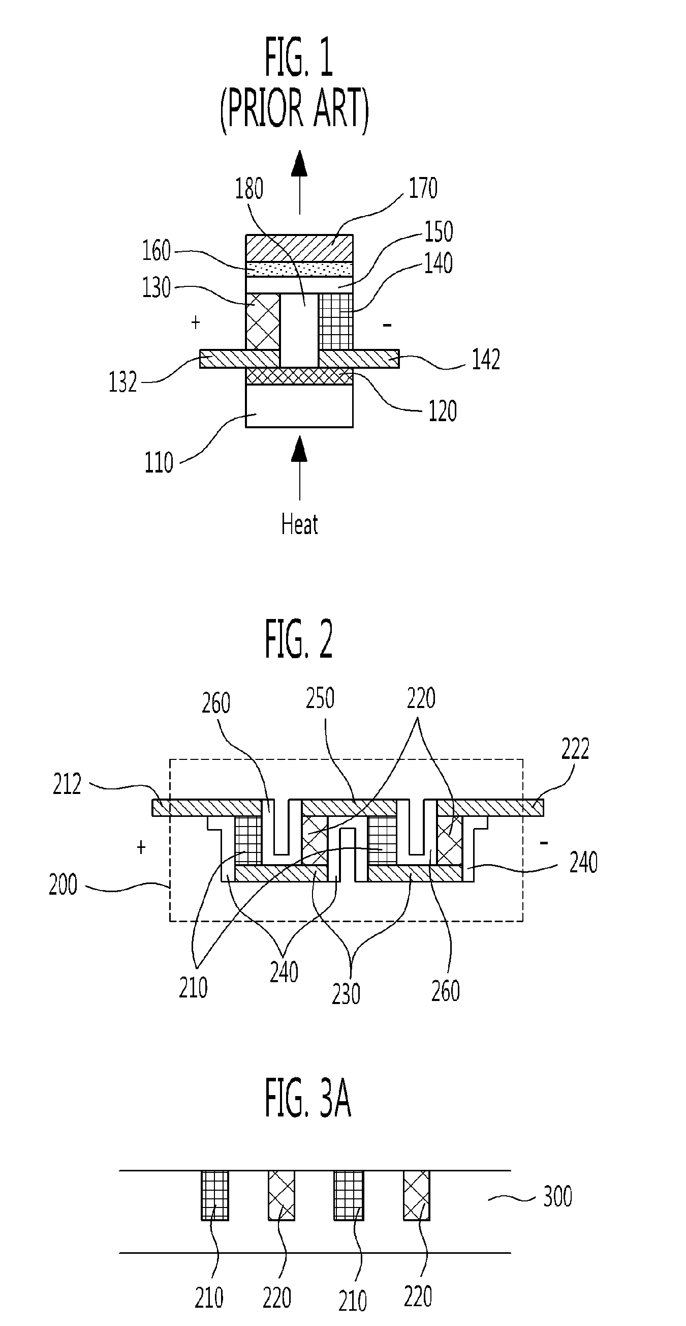
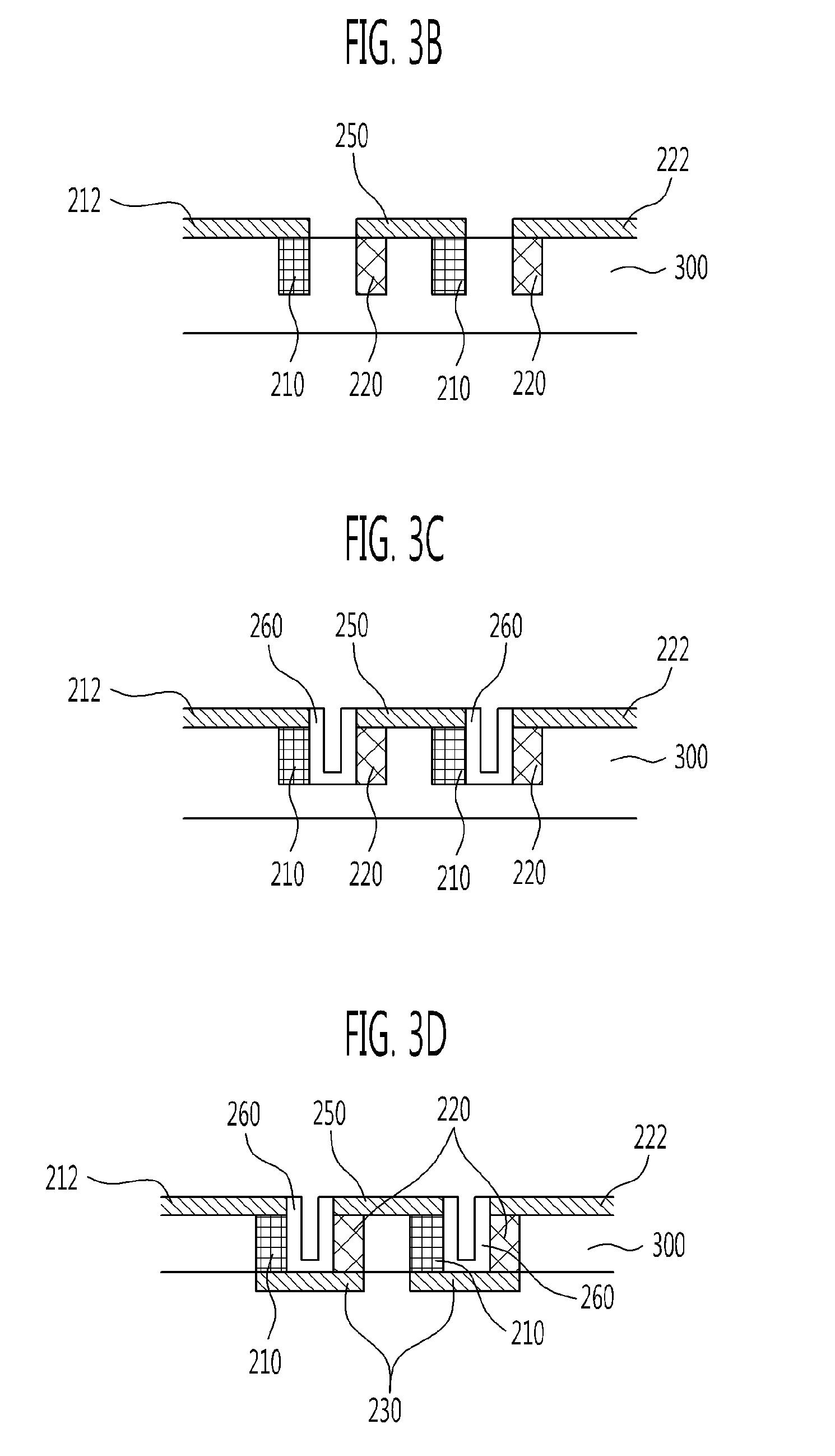
[0027]While the embodiment in accordance with the present invention illustrates two pairs of P-type semiconductors and N-type semiconductors for the convenience of description, the present invention is not limited thereto and the flexible thermoelectric generator in accordance with the present invention may include a plurality of pairs of P-type semiconductors and N-type semiconductors. In addition, the flexible thermoelectric generator may be variously connected in series or in parallel.

[0028]FIG. 2 is a cross-sectional view showing a structure of a flexible thermoelectric generator in accordance with an exemplary embodiment of the present invention.

[0029]Referring to FIG. 2, a f...


PUM


Abstract

Provided are a flexible thermoelectric generator, a wireless sensor node including the same and a method of manufacturing the same. The flexible thermoelectric generator includes a plurality of P-type semiconductors and a plurality of N-type semiconductors, which are alternately arranged, an upper metal for connecting upper surfaces of the adjacent P-type semiconductor and N-type semiconductor, a lower metal for connecting lower surfaces of the adjacent P-type semiconductor and N-type semiconductor, and alternately disposed with respect to the upper metal, a P-type metal connected to at least one P-type semiconductor among the plurality of P-type semiconductors, and an N-type metal connected to at least one N-type semiconductor among the plurality of N-type semiconductors.

Description

CROSS-REFERENCE TO RELATED APPLICATION[0001]This application claims priority to and the benefit of Korean Patent Application No. 10-2009-0128361 filed Dec. 21, 2009, and 10-2010-0024621 filed Mar. 19, 2010, the disclosure of which is incorporated herein by reference in its entirety.BACKGROUND[0002]The present invention relates to a flexible thermoelectric generator, a wireless sensor node including the same and a method of manufacturing the same. More specifically, the present invention relates to a flexible thermoelectric generator, a wireless sensor node including the same and a method of manufacturing the same that are capable of supplying energy generated by a change in temperature instead of a conventional battery and substituting for a conventional temperature sensor using characteristics of a change in output voltage according to the change in temperature.Discussion of Related Art[0003]In recent times, as portable electronic devices and mobile terminals become more widely use...

Claims


Application Information

Patent Timeline
IPC IPC(8): G01K7/02H01L35/32H01L21/30
CPCG01K7/02H01L35/34H01L35/32G01K2215/00H10N10/01H10N10/17
Inventor LEE, JAE WOOYANG, YIL SUKHEO, SE WANJANG, MOON GYUKIM, JONG DAE
Owner ELECTRONICS & TELECOMM RES INST
Learn More