Apparatus and method for counter-resistance exercise

a technology of resistance exercise and apparatus, applied in the field of exercise apparatus and methods, can solve the problems of inertia of high labor intensity, and heavy weights or resistance elements, and achieve the effects of reducing labor intensity, reducing labor intensity, and reducing labor intensity

Inactive Publication Date: 2011-06-23
HORNE EDWARD F
View PDF13 Cites 68 Cited by
  • Summary
  • Abstract
  • Description
  • Claims
  • Application Information

AI Technical Summary

Benefits of technology

[0013]In another embodiment, the force sensing device is a load cell configured to measure the mechanical force applied to the cable and pulley system by a user during a counter-resistance exercise. In another embodiment, the exercise machine further includes a means for adjusting the location of the at least one of a handle and a roller relative to the support.
[0014]In yet another aspect, the invention provides a method for counter-resistance exercise including providing a cable and pulley system having at least one pulley mechanically coupled to a support and at least one substantially inelastic cable configured for engagement with the pulley. The method further includes applying

Problems solved by technology

These weights or resistance elements are typically heavy and often bulky to maneuver, and as a result, present safety concerns.
In addition, the inertia of the weights or resistance elements can produce undesired effects after the exercise is concluded and the weights or resistance elements are returned to the initial exercise position.
Isometric type exercise apparatus and methods do not utilize weights or resistance elements that require adjustment and that are heavy, bulky or potentially dangerous.
However, the apparatus and methods available for isometric type exercise do not allow for a full range of motion of the muscles, and provide the user with only limited control over varying the amount of resistance.
Furthermore, such apparatus and methods do not permit significant variability or customization of a workout, for example a combined heavy resist

Method used


Image

  • Apparatus and method for counter-resistance exercise
  • Apparatus and method for counter-resistance exercise
  • Apparatus and method for counter-resistance exercise

Examples


Embodiment Construction

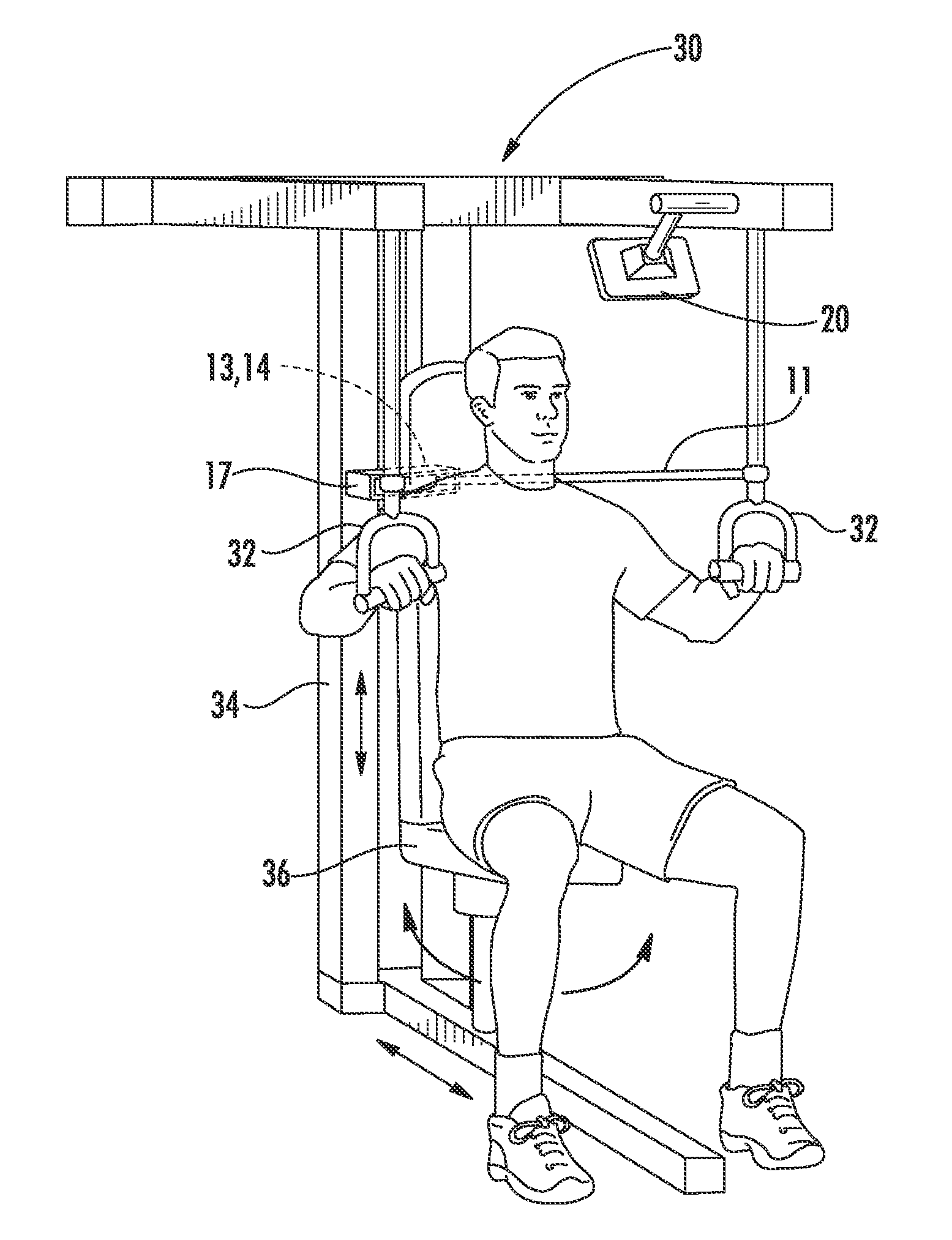
[0023]The accompany drawing figures illustrate various exemplary and preferred embodiments of an apparatus and method for counter-resistance exercise in accordance with the present invention. The exemplary embodiments shown and described herein are intended to illustrate broad concepts of the invention and are not intended to limit the scope of the invention in any manner. In particular, the invention should not be construed as being limited to the particular embodiments and equivalents thereof shown and described herein, or to specific features, advantages or objectives associated therewith.

[0024]As used herein, the term “counter-resistance exercise” is intended to refer to a dynamic (as opposed to static) exercise in which a mechanical force is applied by one muscle or muscle group and is opposed (i.e. resisted) by another muscle or muscle group. Counter-resistance exercises according to the invention are derived from isometric-style push and pull exercises. However, unlike an iso...


PUM


Abstract

An apparatus and method for counter-resistance exercise includes a cable and pulley system and a force sensing device operatively coupled to the cable and pulley system. The cable and pulley system has at least one pulley and at least one substantially inelastic cable configured for engagement with the pulley. The force sensing device is operable to generate data relating to a mechanical force applied to the cable by a user during a counter-resistance exercise in which the mechanical force is applied by a first muscle or muscle group and is opposed by a second muscle or muscle group. In one embodiment, the mechanical force applied to the cable is transferred to a load cell and the load cell converts the mechanical force to a proportional electrical signal. In another embodiment, a wireless transmitter transmits the electrical signal to a display configured for wireless communication with the transmitter and the display provides the user with biometric feedback relating to the exercise.

Description

CROSS REFERENCE To RELATED APPLICATION[0001]This application claims the benefit of U.S. Provisional Application No. 61 / 289,629 filed on Dec. 23, 2009, the entire disclosure of which is incorporated herein by reference.FIELD OF THE INVENTION[0002]The invention relates generally to exercise apparatus and methods of exercise. More particularly, the invention is an apparatus and associated method for counter-resistance exercise including a cable and pulley system, a force sensing device, a transmitter and a biometric feedback display for displaying exercise information to a user.BACKGROUND OF THE INVENTION AND RELATED ART[0003]Numerous isotonic (dynamic) and isometric (static) exercise apparatus and methods of exercise are known. Isotonic exercise apparatus and methods extend and contract the muscles through a range of motion, while isometric exercise apparatus and methods work the muscles against an immovable force, commonly referred to as “overcoming isometric,” or alternatively by op...

Claims


Application Information

Patent Timeline
IPC IPC(8): A63B21/00
CPCA63B21/062A63B24/0062A63B2225/50A63B2220/51A63B2024/0068A63B21/0628
Inventor HORNE, EDWARD F.
Owner HORNE EDWARD F
Why Eureka
Try Eureka