Eye injection device

a technology of eye injection and eye, which is applied in the field of eye injection devices, can solve the problems of awkward positioning and relatively inconvenient placement of the device on the eye surface, and achieve the effect of improving the quality of eye treatmen

Active Publication Date: 2011-06-23
INST NAT DE LA SANTE & DE LA RECHERCHE MEDICALE (INSERM)
View PDF6 Cites 26 Cited by
  • Summary
  • Abstract
  • Description
  • Claims
  • Application Information

AI Technical Summary

Benefits of technology

[0008]As will be set out in more detail later in the description, the locating mark allows the user to position the injection device with remarkable precision on the surface of the eye, before any penetration of the injection needle through the surface thereof. The risk of error is therefore reduced or substantially eliminated.
[0132]a support on which the invasive electrode is fixed or which can guide a sliding movement of said invasive electrode,said device having a locating mark disposed in such a way that said locating mark can be placed in contact with a defined bearing region of the surface of the eye, before any contact of the invasive electrode with said surface, and can then be kept in contact with said bearing region during a normal penetration of said invasive electrode through said surface of the eye.

Problems solved by technology

The placement of this device on the surface of the eye is awkward.
In addition, the positioning is relatively imprecise.
Finally, an error in positioning requires multiplying the punctures in the eye in order to reposition the device.

Method used


Image

  • Eye injection device
  • Eye injection device
  • Eye injection device

Examples


Embodiment Construction

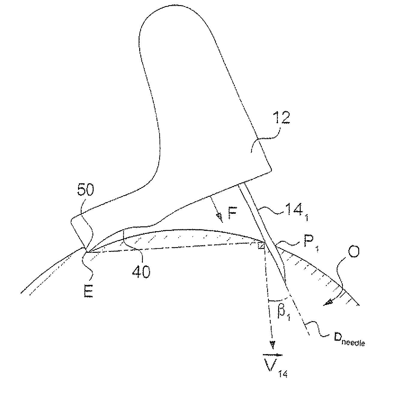
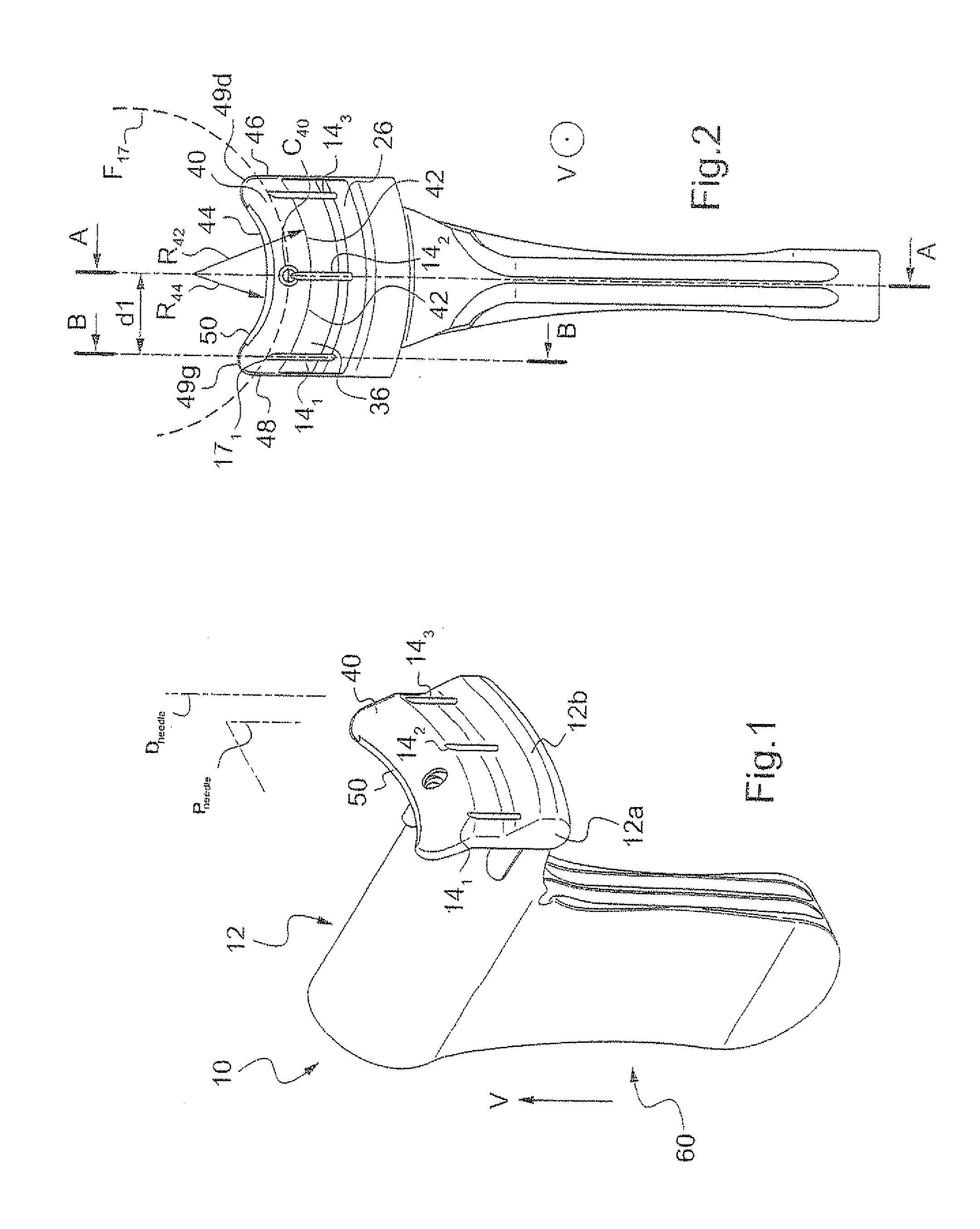
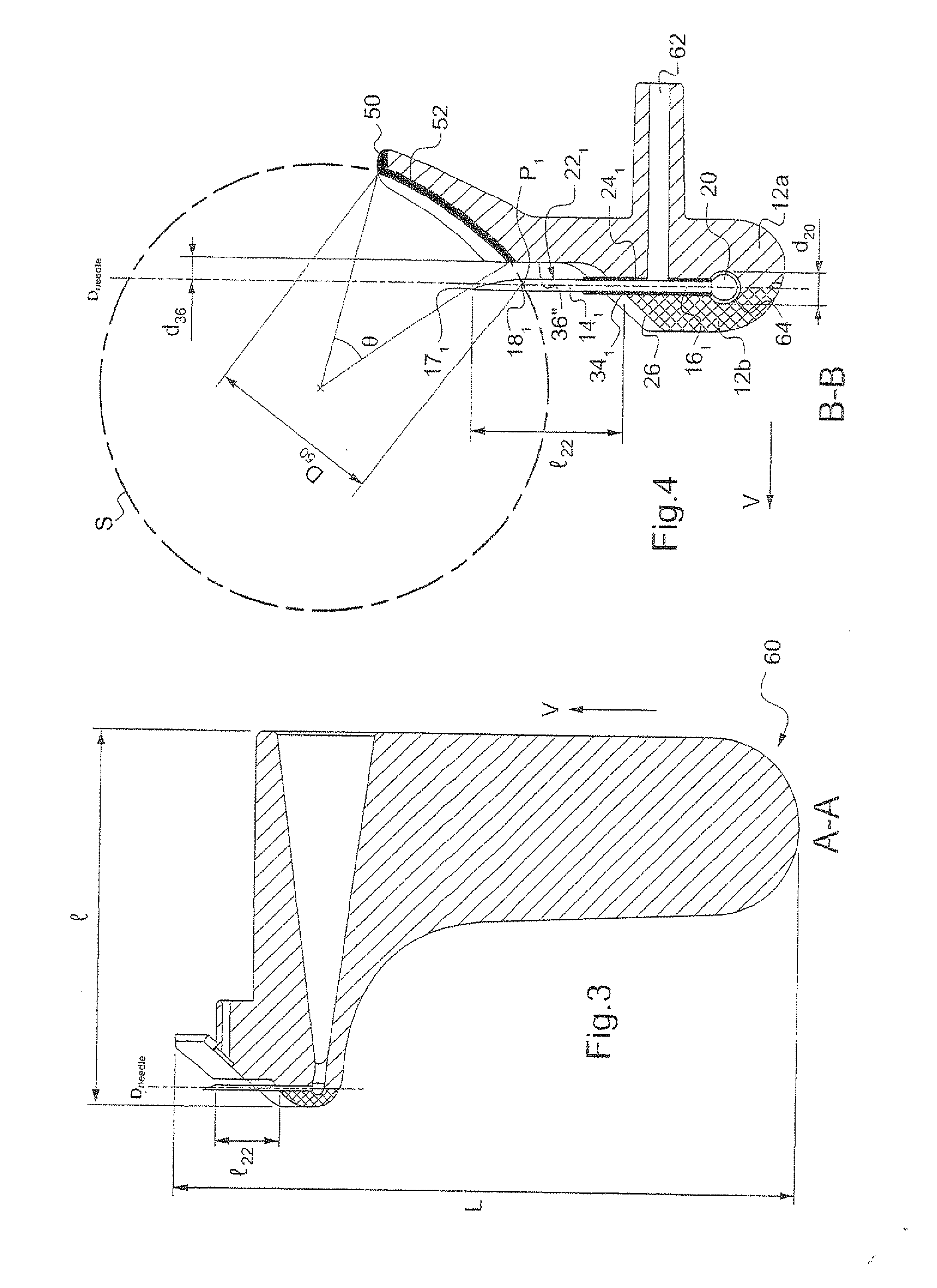
[0183]The injection device 10 shown in FIGS. 1 to 4 comprises a support 12 on which are fixed three identical and rectilinear injection needles 141, 142 and 143 oriented parallel to one another in a needle direction Dneedle.

[0184]The three injection needles belong to one and the same plane, called the “plane of the needles” and designated Pneedles.

[0185]In order to be secured on the support 12, the injection needles are sandwiched between a main part 12a of the support 12 and a blocking piece 12b, which is fixed on the main part 12a, for example by clipping, by adhesive bonding or by fusion of material.

[0186]The needle 142 extends at an equal distance between the needles 141 and 143. The distance d1 between the needle 142 and the needles 141 and 143 can be greater than 3 mm or 3.5 mm or 4 mm and less than 6 mm or 5.5 mm. In particular, it can be about 4.5 mm (FIG. 2).

[0187]Since the three needles are identical and are fixed in a similar manner on the support, only the needle 141 is ...


PUM


Abstract

An injection device for injecting a product into an eye, said device comprising an injection needle and a support on which the injection needle is fixed, said device being characterized in that it comprises a locating mark disposed in such a way that the latter can be placed in contact with a defined bearing region of the surface of the eye, before any contact of the injection needle with said surface, and can then be kept in contact with said bearing region during a stage of penetration of said injection needle through said surface of the eye.

Description

TECHNICAL FIELD[0001]The present invention relates to a device for injecting a product into an eye and / or for electroporation.PRIOR ART[0002]WO 2006 / 123248 describes a device for administering a product by electroporation. In the embodiment shown in FIG. 16, the device is designed such that it can be applied to the surface of the eye, and it has a needle permitting an injection of product. The placement of this device on the surface of the eye is awkward. In addition, the positioning is relatively imprecise. Finally, an error in positioning requires multiplying the punctures in the eye in order to reposition the device.[0003]WO 00 / 07530, WO 2007 / 052730 and WO 2006 / 052557 describe injection devices. These devices do not comprise an injection needle fixed on a support designed to bear on the surface of the eye, nor do they have a locating mark designed to bear on the edge of the cornea of an eye, before any contact of the injection needle with the eye, and then to be kept in this bear...

Claims


Application Information

Patent Timeline
Patent Type & Authority Applications(United States)
IPC IPC(8): A61F9/00A61M5/42
CPCA61F9/0017A61N1/327A61N1/306A61F9/0026A61F9/0008
Inventor TOUCHARD, ELODIEKOWALCZUK, LAURABEHAR-COHEN, FRANCINE
Owner INST NAT DE LA SANTE & DE LA RECHERCHE MEDICALE (INSERM)
Why Eureka
Try Eureka