Flow control valve and a method of assembling a flow control valve

a flow control valve and assembly method technology, applied in the direction of valve housings, functional valve types, operating means/releasing devices of valves, etc., can solve the problems of difficult management of individual parts of flow control valves, and achieve the effect of convenient assembly

Active Publication Date: 2013-08-15
DANFOSS AS
View PDF12 Cites 11 Cited by
  • Summary
  • Abstract
  • Description
  • Claims
  • Application Information

AI Technical Summary

Benefits of technology

[0006]It is an object of embodiments of the invention to provide a flow control valve which is easier to assemble than prior art flow control valves.
[0008]It is an even further object of embodiments of the invention to provide a method for assembling a flow control valve, the method being easier to perform than prior art assembly methods.
[0019]The frame part is attached directly to the first housing part or to the second housing part. Thereby the frame part, along with the valve element, the moving mechanism and the actuating mechanism mounted thereon, can be attached to the first / second housing part before the first housing part and the second housing part are attached to each other. This may even be performed at an assembly line arranged remotely from the operating site of the flow control valve. Consequently, the final assembly step performed at the operating site of the flow control valve when the valve is installed requires only attaching the first and second housing parts to each other. This is very simple, and the risk of performing errors during the assembly is considerably reduced. Furthermore, it is much easier and more cost effective to perform the complicated part of the assembly process at an assembly line, than it is to perform it at the operating site, where space may be limited, access angles may be awkward, and personnel may not be specialized.
[0022]The frame part may define a central cavity and a peripheral cavity. In this case the moving mechanism may be at least partly accommodated in the central cavity of the frame part, and the movable valve element may be at least partly accommodated in the peripheral cavity of the frame part. This construction provides a compact design of the flow control valve, in particular because the movements of the valve element take place in the peripheral cavity, and the available space in the interior part of the housing is thereby utilised in a very efficient manner. As an alternative construction, it may be envisaged that the moving mechanism may be at least partly accommodated in the peripheral cavity of the frame part, and that the movable valve element may be at least partly accommodated in the central cavity of the frame part.
[0041]It is an advantage that the valve part, the moving mechanism and the actuating mechanism are mounted on the frame part, and that the frame part is subsequently attached to one of the housing parts before the housing parts are attached to each other to form the final flow control valve, because this makes the manufacturing process easy, and because it minimises the number of assembling steps and the number of parts at the operating site of the flow control valve. Therefore the manufacturing process is efficient and cost effective, and the risk of errors during the assembly of the flow control valve is minimised. Furthermore, it allows the major part of the assembly process to take place at a manufacturing site. This makes the assembly process easy and cost effective, and it minimises the risk of errors, as described above.
[0042]The method may further comprise the step of fixing the frame part to a manufacturing table prior to performing the mounting step, and the mounting step may be performed while the frame part is fixed to the manufacturing table. According to this embodiment, the frame part is kept in a fixed position while the mounting step is performed. Furthermore, the frame part may be kept in a position and an orientation which makes it as easy as possible to perform the mounting step. This facilitates the manufacturing process. Finally, the mounting step may be performed in a location which is remote from the operating site of the flow control valve, such as at a manufacturing site. This makes the manufacturing process efficient and cost effective, as described above.

Problems solved by technology

This is cumbersome and makes it difficult to manage the individual parts of the flow control valve.

Method used


Image

  • Flow control valve and a method of assembling a flow control valve
  • Flow control valve and a method of assembling a flow control valve
  • Flow control valve and a method of assembling a flow control valve

Examples


first embodiment

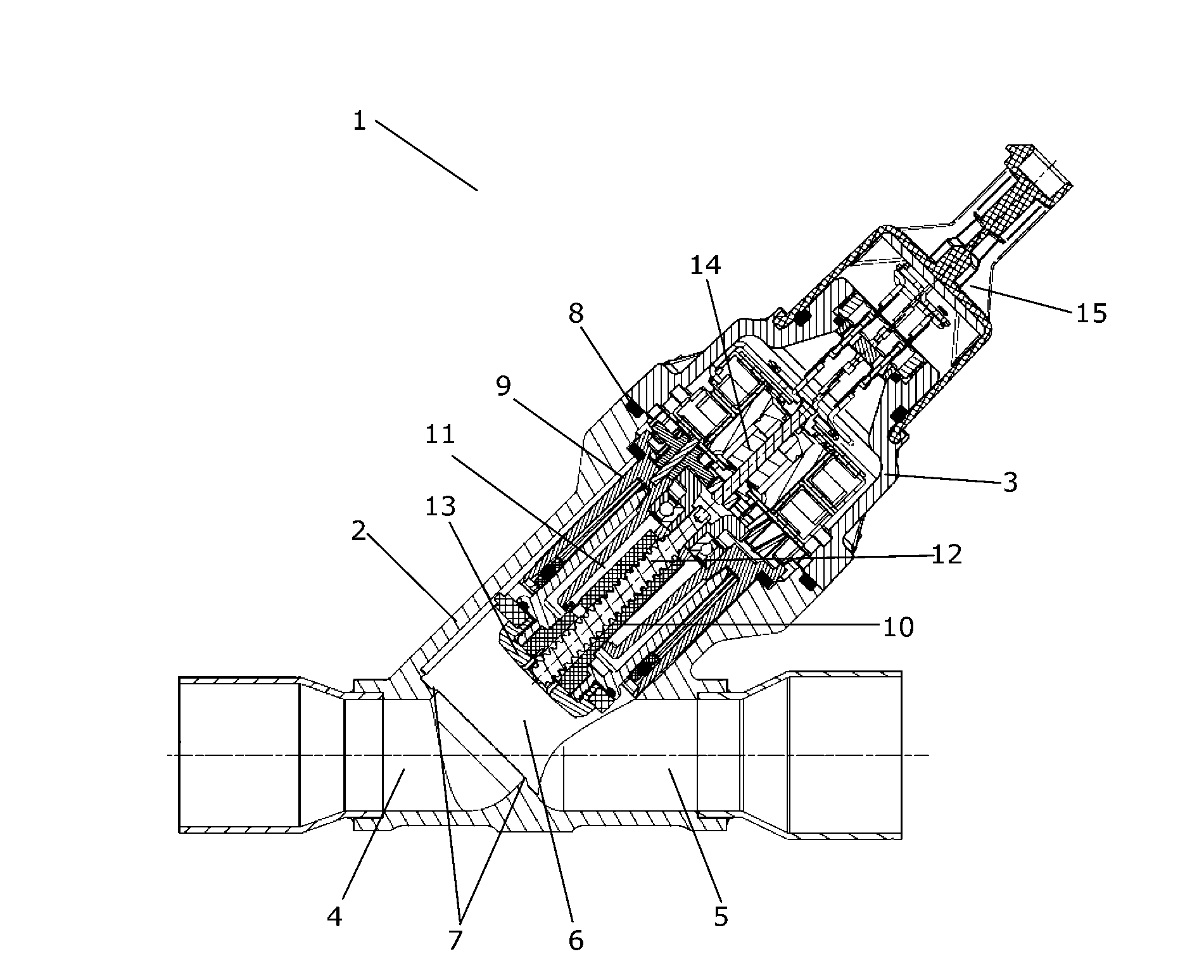
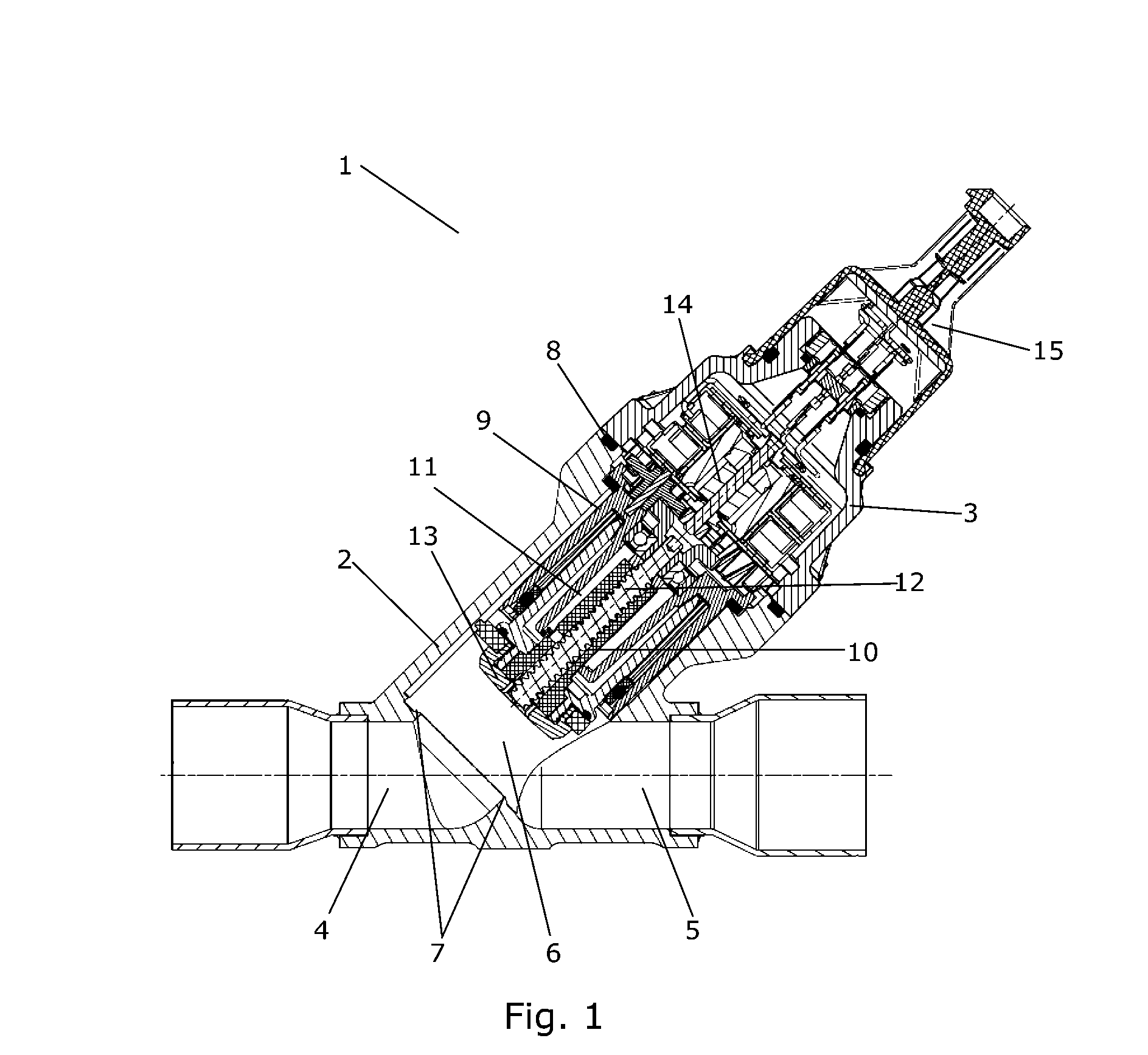
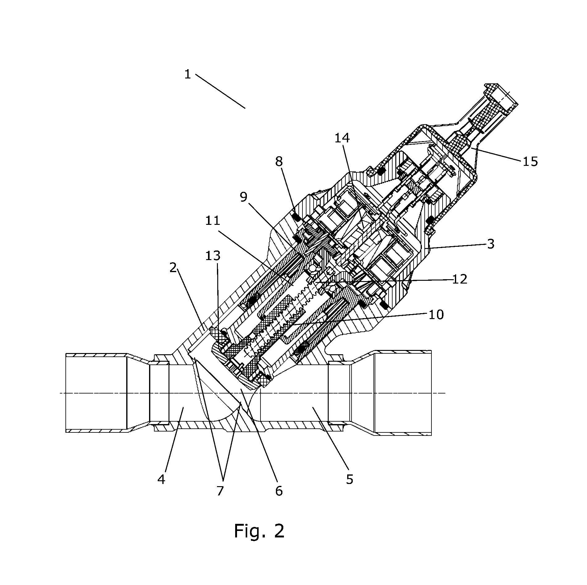
[0053]FIGS. 1-3 are cross sectional views of a flow control valve 1 according to the invention. In FIG. 1 the flow control valve 1 is shown in a fully open position, in FIG. 2 the flow control valve 2 is shown in a partly open position, and in FIG. 3 the flow control valve 1 is shown in a fully closed position. This will be explained further below.

[0054]The flow control valve 1 comprises a first housing part 2 and a second housing part 3. The first housing part 2 defines a first flow section 4 and a second flow section 5. A connecting port 6 fluidly interconnects the first flow section 4 and the second flow section 5, and a valve seat 7 is arranged at the connecting port 6.

[0055]During operation of the flow control valve 1, the first flow section 4 may operate as a fluid inlet of the flow control valve 1, and the second flow section 5 may operate as a fluid outlet of the flow control valve 1. In this case, the first flow section 4 receives fluid from a fluid source. The fluid flows ...

second embodiment

[0069]FIG. 7 is a perspective view of a flow control valve 1 according to the invention. Similarly to the embodiment shown in FIGS. 1-3, the flow control valve 1 of FIG. 7 is provided with a first housing part 2 and a second housing part 3, the first housing part 2 and the second housing part 3 being attached to each other in such a manner that a substantially closed housing is formed, the housing defining an outer boundary of the flow control valve 1.

[0070]The second housing part 3 is provided with a connector part 15 which establishes electrical connections between the interior of the housing and the exterior, thereby allowing power supply to power consuming components arranged in the interior of the housing.

[0071]FIG. 8 is a cross sectional view of the flow control valve 1 of FIG. 7. The first housing part 2 defines a first flow section 4 and a second flow section 5. Fluid can flow from the first flow section 4 to the second flow section 5, or vice versa, via a connecting port 6,...


PUM


Abstract

A flow control valve (1) and a method for assembling a flow control valve (1) are disclosed. The flow control valve (1) comprises a first housing part (2) and a second housing part (3) attached directly to each other, in such a manner that the first housing part (2) and the second housing part (3) form a substantially closed housing. The first housing part (2) defines a first flow section (4), a second flow section (5), a connecting port (6) fluidly interconnecting the first flow section (4) and the second flow section (5), and a valve seat (7) arranged at the connecting port (6). The flow control valve (1) further comprises a frame part (9) arranged in an interior part of the housing formed by the first housing part (2) and the second housing part (3), the frame part (9) having mounted thereon a valve element (10, 13) arranged movably relative to the valve seat (7), a moving mechanism, e.g. including a spindle (12), for moving the valve element (10, 13), and an actuating mechanism, e.g. a stepper motor (14), for operating the moving mechanism. The frame part (9) is attached directly to the first housing part (2) or to the second housing part (3). The frame part (9) along with the components mounted thereon can be mounted on the first (2) or second (3) housing part during the assembly of the flow control valve (1). The final assembly step thereby only includes attaching the first (2) and second (3) housing parts to each other. This makes the assembly process easy, thereby reducing the risk of errors.

Description

CROSS REFERENCE TO RELATED APPLICATIONS[0001]This application is entitled to the benefit of and incorporates by reference essential subject matter disclosed in International Patent Application No. PCT / DK2011 / 000109 filed on Oct. 5, 2011 and Danish Patent Application No. PA 2010 00905 filed Oct. 6, 2010.FIELD OF THE INVENTION[0002]The present invention relates to a flow control valve, in particular a flow control valve for a vapour compression system, such as a refrigeration system or a heat pump. More particularly, the flow control valve of the present invention is easier to assemble than prior art flow control valves. The present invention further relates to a method for assembling a flow control valve.BACKGROUND OF THE INVENTION[0003]Flow control valves are used for controlling fluid flows in a variety of applications. For instance, in vapour compression systems, such as refrigeration systems, air condition systems or heat pumps, flow control valves are, e.g., used for controlling...

Claims


Application Information

Patent Timeline
Patent Type & Authority Applications(United States)
IPC IPC(8): F16K31/04F16K99/00F16K1/02
CPCF16K31/04F16K27/029F16K99/00F16K31/047F16K1/02Y10T137/0491
Inventor NISSEN, BIRTHE REESEPORLAND, JOHNANDERSEN, EJNER KOBBEROEVAN BEEK, JOHANBIRKELUND, MICHAELABRAMOWICZ, MARCIN
Owner DANFOSS AS
Why Eureka
Try Eureka