
Internal television antenna and method for a portable entertainment module

a technology for portable entertainment modules and antennas, applied in the direction of resonant antennas, television systems, non-resonant long antennas, etc., can solve the problems of increasing the size of portable televisions, set of design limitations, and shortening the wave length

Inactive Publication Date: 2011-06-23
WINEGARD
View PDF7 Cites 250 Cited by
  • Summary
  • Abstract
  • Description
  • Claims
  • Application Information

AI Technical Summary

Benefits of technology

[0013]The summary set forth above does not limit the teachings of the invention especially as to variations and other emb...

Problems solved by technology

This antenna design increases the size of the portable television.
The form factor for such small portable entertainment modules provides a set of design limitations that are critical in the concept and implementation of an internal television antenna design.
The main design limitation comes from the wave length shortening due the size constraint which in most cases is greater than 20 times. A second design limitation comes from the shape used for the antenna inside the module.
The shape is limited by the module design itself and the arrangement and placement of various components, air vents, and other physical structures that can be in close proximity to the antenna.
A third design limitation concerns the materials used for the antenna that often requires special technologies for printing and etching.

Method used


Image

  • Internal television antenna and method for a portable entertainment module
  • Internal television antenna and method for a portable entertainment module
  • Internal television antenna and method for a portable entertainment module

Examples


Embodiment Construction

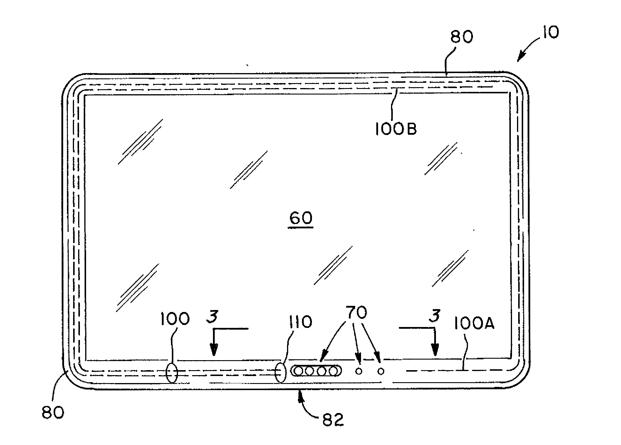
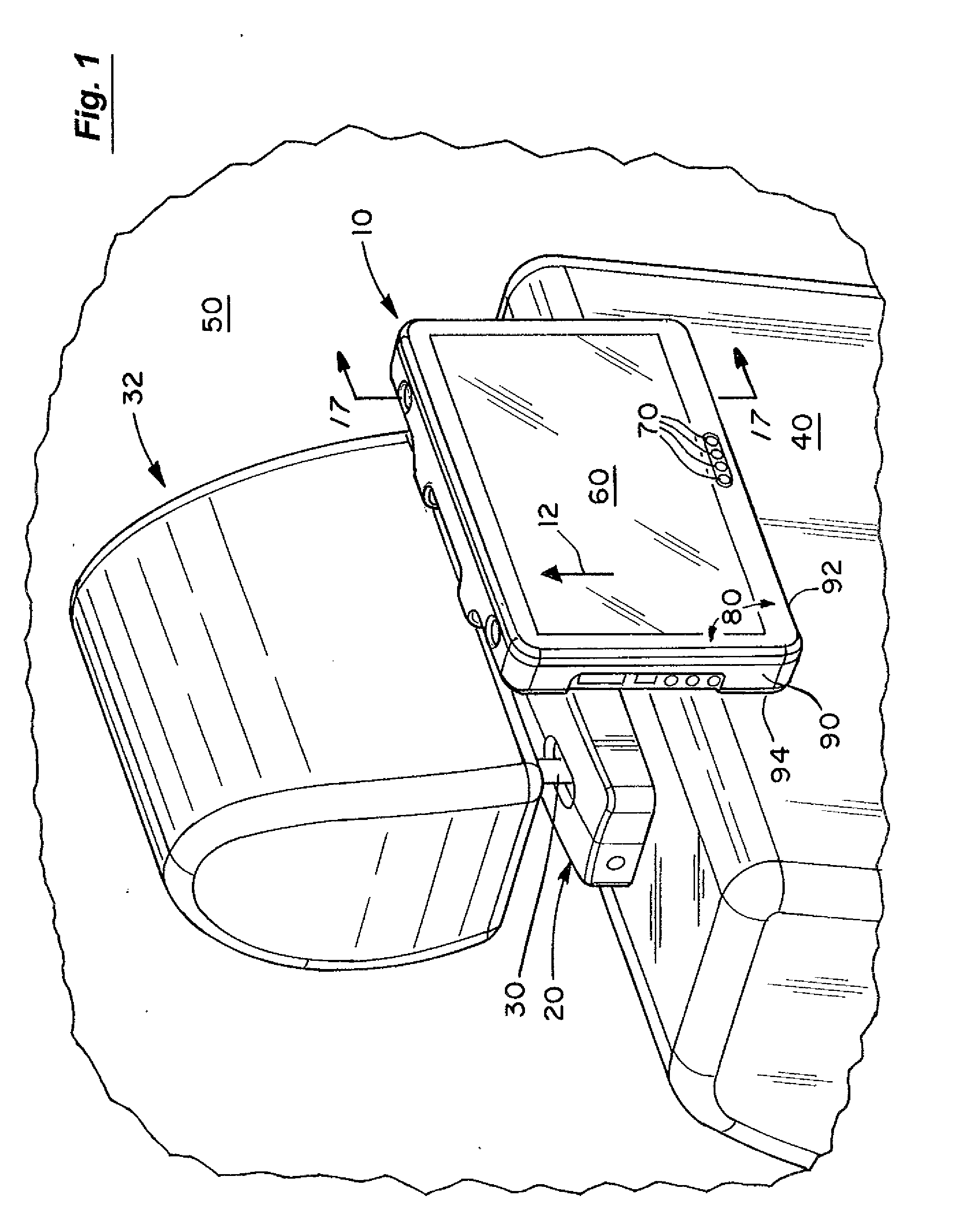
[0037]FIG. 1 shows a small portable entertainment module 10 docked to a head rest mount 20 connected to the posts 30 of a head rest 32 of a seat 40 within a vehicle 50. The portable entertainment module 10 can be removed in any suitable fashion from the mount 20 such as by moving the module 10 in the direction of arrow 12. The module 10 can then be hand carried for use in or out of the vehicle 50 such as outdoors or docked on any suitable mount or docking station located elsewhere. FIG. 1 is showing one embodiment of the portable entertainment module of the present invention, other embodiments are not limited to being connected to head rest posts. Indeed, the module 10 can be a hand held module for use in a residence, outside, etc.

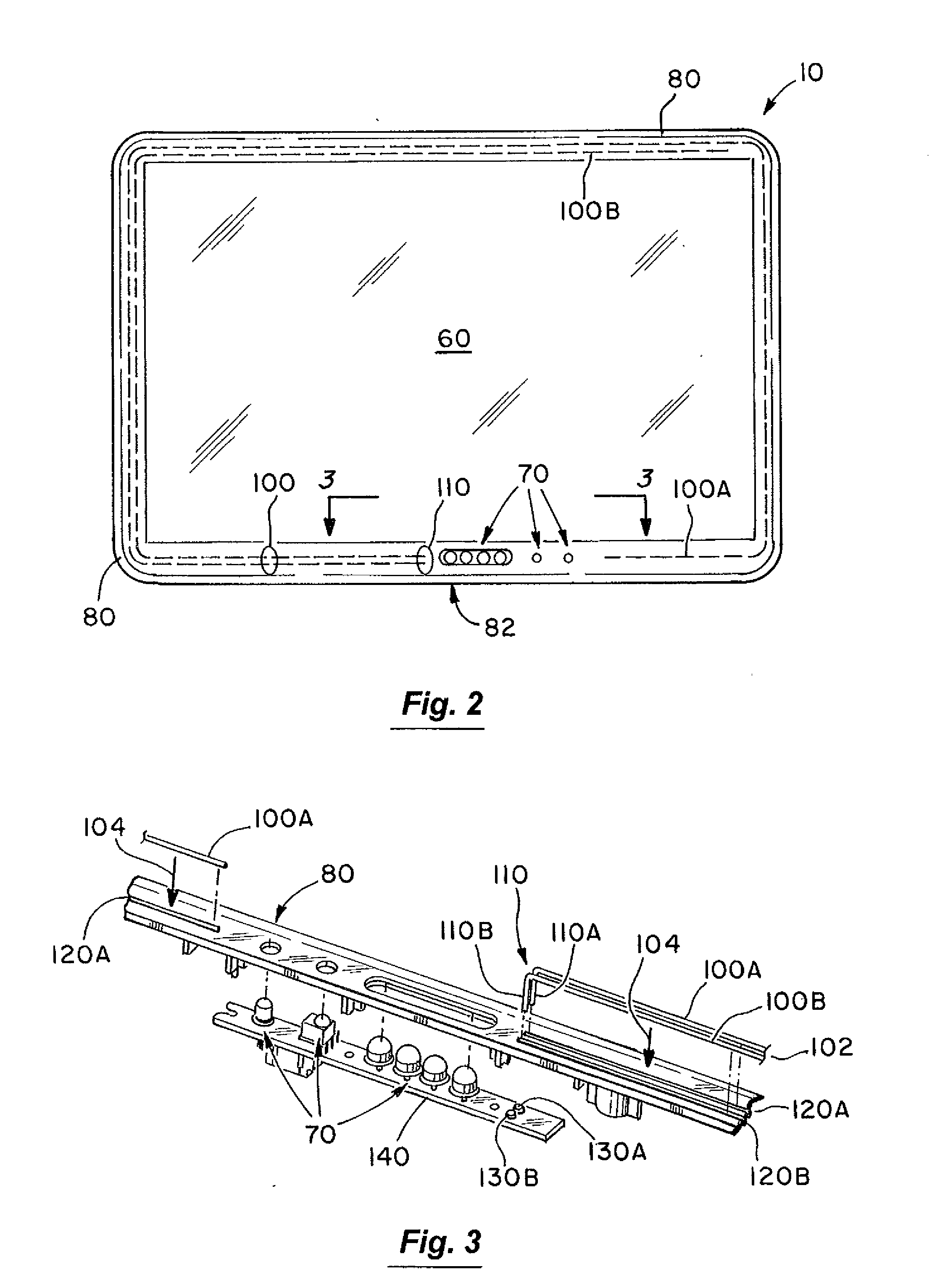
[0038]While the module 10 has a number of entertainment uses (such as playing games, DVDs, etc.), one use is to receive broadcast digital television signals. The present invention provides one built-in antenna, in one embodiment, or a pair of built-in ante...


PUM


Abstract

An apparatus and method using a front internal dual band television antenna or a pair of internal dual band antennas for a portable entertainment module having a housing and a display screen. A front spiral antenna is embedded in the housing around the periphery of the display screen and is tuned to compensate for the influence nearby components. A rear logo-periodic antenna is located inside the rear of the housing and is modified to have various environmental openings to fit around existing components, vents and structures in the housing. Any pair of different antenna architectures could be used.

Description

RELATED APPLICATIONS[0001]This application claims the benefit of U.S. Provisional Patent Application Ser. No. 61 / 287,310 filed Dec. 17, 2009.BACKGROUND OF THE INVENTION[0002]1. Field of the Invention[0003]The invention relates to antennas for receiving broadcast digital television signals and, more particularly, to internal dual band television antennas for small portable entertainment modules for use in vehicles and elsewhere.[0004]2. Discussion of the Background[0005]A wide variety of different architectures for automotive antennas exist for a number of uses. Amplified rod antennas that mount to the exterior such as on the roof of a vehicle are used for different frequency bands such as AM and FM reception. Antennas printed on windshield glass are used for reception of AM, FM, and TV signals. Antennas exist for vehicles that receive satellite signals such as GPS, XM and Sirius signals. Cell phone antennas for vehicles use also exist. Other antennas such as fractal antennas, integr...

Claims


Application Information

Patent Timeline
IPC IPC(8): H04N7/16H01Q1/24
CPCH01Q1/24H01Q9/27H01Q21/30H01Q11/10H01Q21/28H01Q9/42
Inventor STANTCHEV, GEORGE HRISTOV
Owner WINEGARD
Learn More