
Lamp and lamp holder module thereof

Inactive Publication Date: 2011-06-30
LITE ON ELECTRONICS (GUANGZHOU) LTD +1
View PDF1 Cites 10 Cited by
  • Summary
  • Abstract
  • Description
  • Claims
  • Application Information

AI Technical Summary

Benefits of technology

[0007]Accordingly, the lamp of this invention includes a light-emitting module and a lamp holder module. The lamp holder module permits the light-emitting module to be removably disposed therein so that the light-emitting module can be removed from or installed in the lamp holder module independently.
[0009]The effect of this invention resides in that, by virtue of the configuration of the pressing mechanism, the light-emitting module can be pressed into position by the pressing member, so that, when the light-emitting module is damaged, a user may remove the light-emitting module independently for repair or replacement, and does not need to dispose of the other functioning components. This not only can reduce maintenance and replacement costs, waste of functioning components can also be avoided.

Problems solved by technology

Therefore, when a light-emitting chip of the light-emitting diode is damaged, it is difficult to remove the light-emitting diode independently for repair or replacement.
As such, the replacement and maintenance costs are relatively high, and other functioning components are wasted.

Method used


Image

  • Lamp and lamp holder module thereof
  • Lamp and lamp holder module thereof
  • Lamp and lamp holder module thereof

Examples


Embodiment Construction

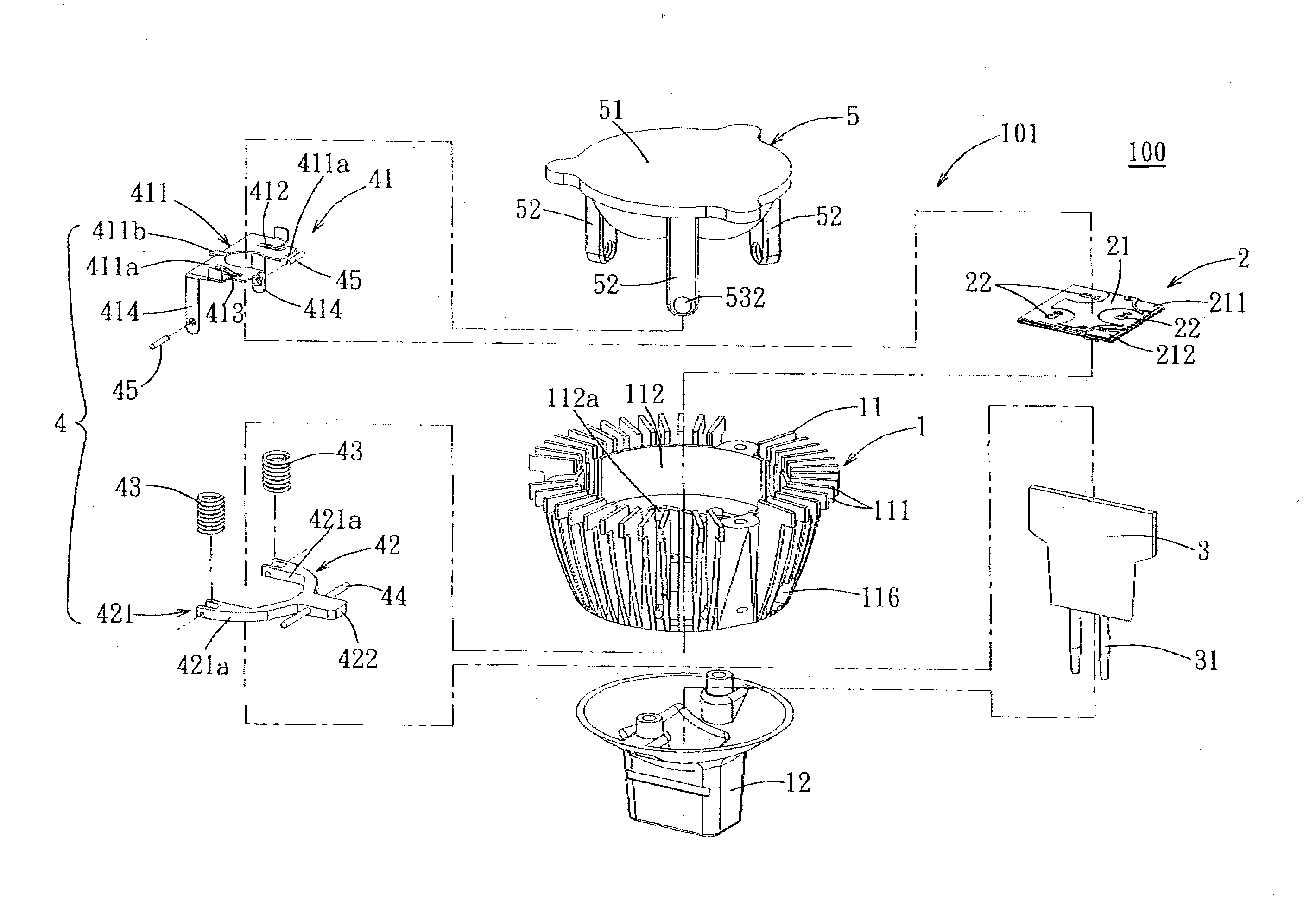
[0018]FIG. 1 is an exploded perspective view of the preferred embodiment of a lamp 100 according to the present invention. The lamp 100 includes a lamp holder module 101, a light-emitting module 2 disposed on the lamp holder module 101, and a circuit unit 3.

[0019]The light-emitting module 2 includes a substrate 21 and a plurality of light-emitting chips 22 disposed fixedly on the substrate 21. Certainly, the number of the light-emitting chips 22 is not limited to what is disclosed herein. The light-emitting module 2 may include only one light-emitting chip 22, depending on the required luminosity. The substrate 21 may be a circuit board or a ceramic substrate, and has a first electrode contact 211 and a second electrode contact 212 which are coupled electrically to the light-emitting chips 22. In this embodiment, the first electrode contact 211 and the second electrode contact 212 are both exposed from a top face of the substrate 21.

[0020]The lamp holder module 101 includes a body 1...


PUM


Abstract

A lamp includes a lamp holder module and light-emitting module disposed in the lamp holder module. The lamp holder module includes a body, a pressing mechanism disposed on the body, and an upper cover engaging removably the body. The light-emitting module is placed on the body and is pressed into position through the pressing mechanism. The pressing mechanism is operable to release the light-emitting module, thereby facilitating removal and installation of the light-emitting module. The upper cover serves as a lens of the light-emitting module and covers the light-emitting module.

Description

CROSS-REFERENCE TO RELATED APPLICATION[0001]This application claims priority of Chinese Patent Application No. 200910265434.3, filed on Dec. 28, 2009.BACKGROUND OF THE INVENTION[0002]1. Field of the Invention[0003]The invention relates to a lamp and a lamp holder, more particularly to a lamp having a light source that is easily removed or installed, and a lamp holder of the lamp.[0004]2. Description of the Related Art[0005]Taiwanese Utility Model No. M343110 discloses a conventional light-emitting diode lamp, wherein a light-emitting diode is disposed in a lamp housing and a circuit board provided with a circuit unit is disposed in a sealed hood coupled to a lower portion of the lamp housing. The light-emitting diode and the circuit board are coupled electrically via soldering wires. Therefore, when a light-emitting chip of the light-emitting diode is damaged, it is difficult to remove the light-emitting diode independently for repair or replacement. Sometimes, the whole lamp is rep...

Claims


Application Information

Patent Timeline
IPC IPC(8): H01J61/52H01J5/48H01K1/30
CPCF21V19/04F21Y2101/02F21V19/0045F21V17/16F21V29/773F21K9/137H01L2924/0002F21V17/162H01L2924/00F21K9/233F21Y2115/10
Inventor WANG, YAN-YUCHEN, CHEN-YULIANG, CHIH-LUNGCHENG, SHUN-CHUNG
Owner LITE ON ELECTRONICS (GUANGZHOU) LTD
Learn More