Exhaust system for a vehicular positive ignition internal combustion engine

a technology of positive ignition and exhaust system, which is applied in the direction of machines/engines, metal/metal-oxide/metal-hydroxide catalysts, etc., can solve the problems of insufficient temperature in the filter to reliably combust particulate matter in on-test cycle or real-world driving conditions, high cost of solutions, and fuel penalty for drivers, so as to reduce the frequency of active interventions and raise the filter

Active Publication Date: 2011-06-30
JOHNSON MATTHEY PLC
View PDF11 Cites 118 Cited by
  • Summary
  • Abstract
  • Description
  • Claims
  • Application Information

AI Technical Summary

Benefits of technology

[0046]We have now discovered, very surprisingly, that it is possible to design an exhaust system for a vehicular positive ignition internal combustion engine wherein the filter temperature attains temperatures sufficient passively to combust particulate matter during at least a portion of a legislative drive cycle, or at least to significantly reduce the frequency of active interventions, e.g. by injecting additional hydrocarbon, to raise filter temperature.

Problems solved by technology

However, we have found that when a filter catalysed with a TWC is located on a vehicle underfloor and downstream of a commercially available close-coupled (flow-through) TWC, the temperature in the filter is insufficient reliably to combust particulate matter in on-test cycle or real-world driving conditions.
However, such solutions are expensive, technically complicated and ultimately result in a fuel penalty to the driver, i.e. increased fuel consumption.

Method used


Image

  • Exhaust system for a vehicular positive ignition internal combustion engine
  • Exhaust system for a vehicular positive ignition internal combustion engine
  • Exhaust system for a vehicular positive ignition internal combustion engine

Examples


example 1

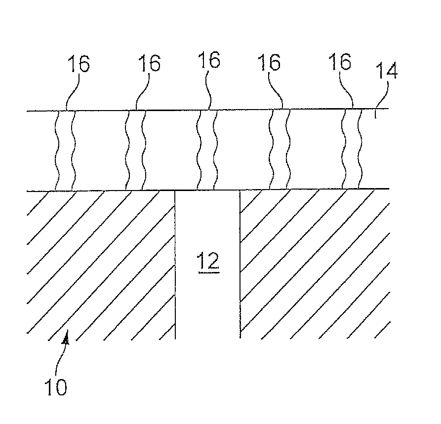
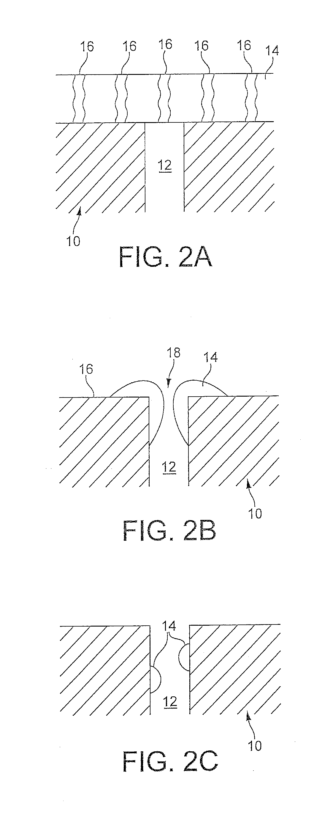
[0118]Two TWC coatings were prepared at a washcoat loading of 2.4 g / in−3 and a precious metal loading of 85 g / ft3 (Pd:Rh 16:1); one was milled to a small particle size (d90<5 μm) that would be expected to pass into the pore structure of a wallflow filter (“in-wall”), while the other was less milled (d90<17 μm) so that it would be expected preferentially to locate more at the surface of a wallflow filter wall (“on-wall”). The coatings were applied to 4.66×4.5 inch 300 cells per square inch cordierite wallflow filter substrates having 12 thousandths of an inch wall thickness (“300 / 12”) with a nominal average pore size of 20 micrometers (hereinafter “microns”) (62% porosity). Each filter was hydrothermally oven-aged at 980° C. for 4 hours and installed in a close-coupled position on a Euro 5 passenger car with a 1.4 L direct injection gasoline engine. Each filter was evaluated over a minimum of three MVEG-B drive cycles, measuring the reduction in particle number emissions relative to ...

example 2

[0122]5.66×3 inch cordierite wallflow filter substrates with a cell density of 300 cells per square inch and a wall thickness of 12 thousandths of an inch (approximately 0.3 mm) were coated with a TWC coating at a washcoat loading of 0.8 g / in3 and a palladium loading of 80 g / ft3. Three pore structures were compared: a nominal average pore size of 38 microns at 65% porosity, a nominal average pore size of 20 microns at 62% porosity and a nominal average pore size of 15 microns at 52% porosity. Each filter was hydrothermally oven-aged at 980° C. for 4 hours and installed in the underfloor position on a Euro 4 passenger car with a 1.4 L direct injection gasoline engine, with a fully formulated TWC coated on a flowthrough substrate monolith located in the close-coupled position, i.e. upstream of the filter. Each filter was evaluated over a minimum of three MVEG-B drive cycles, measuring the reduction in particle number emissions relative to a reference system, wherein the underfloor fil...

example 3

[0124]4.66×4.5 inch, 300 / 12 cordierite wallflow filter substrates with a nominal average pore size of 20 microns and porosity of 62% were coated with a TWC coating at washcoat loadings of 0.8, 1.6 and 2.4 g / in3 respectively. Each sample had a precious metal loading of 85 g / ft3 (Pd:Rh 16:1). Each filter was hydrothermally oven-aged at 980° C. for 4 hours and installed in a close-coupled position on a Euro 4 passenger car with a 1.4 L direct injection gasoline engine. Each filter was evaluated over a minimum of three MVEG-B drive cycles, measuring the reduction in particle number emissions relative to a reference catalyst, wherein the close-coupled filter was exchanged for a TWC coated on a flowthrough substrate monolith at an identical washcoat and precious metal loading, the backpressure differential and the conversion efficiency for gaseous HC, CO and NOx emissions were determined between sensors mounted upstream and downstream of the filter (or reference catalyst). Only non-methan...


PUM

PropertyMeasurementUnit
pore sizeaaaaaaaaaa
pore sizeaaaaaaaaaa
mean sizeaaaaaaaaaa

Abstract

An exhaust system for a vehicular positive ignition internal combustion engine comprises a filter for filtering particulate matter from exhaust gas emitted from the engine, which filter comprising a porous substrate having inlet and outlet surfaces, wherein the inlet surfaces are separated from the outlet surfaces by a porous structure containing pores of a first mean pore size, wherein the porous substrate is coated with a three-way catalyst washcoat comprising a plurality of solid particles wherein the porous structure of the washcoated porous substrate contains pores of a second mean pore size, which is less than the first mean pore size, and a three-way catalyst washcoat disposed on a separate substrate monolith located upstream of the filter, wherein a mass of three-way catalyst washcoat on the upstream substrate monolith is ≦75% of the total mass of three-way catalyst washcoat in the exhaust system.

Description

CROSS-REFERENCE TO RELATED APPLICATIONS[0001]This application claims priority of British Patent Application No. 0922612.7, filed Dec. 24, 2009; British Patent Application No. 1003244.9, filed Feb. 26, 2010; and British Patent Application No. 1014027.5, filed Aug. 23, 2010, the disclosures of which are incorporated herein by reference in their entirety for all purposes.FIELD OF THE INVENTION[0002]The present invention relates to an exhaust system for treating particulate matter (PM) in exhaust gas from a vehicular positive ignition internal combustion engine, particularly for stoichiometrically-operated positive ignition engines but which is also suitable for lean-burn positive ignition engines, which system comprising a filter for use in treating the PM.BACKGROUND OF THE INVENTION[0003]Positive ignition engines cause combustion of a hydrocarbon and air mixture using spark ignition. Contrastingly, compression ignition engines cause combustion of a hydrocarbon by injecting the hydroca...

Claims


Application Information

Patent Timeline
Patent Type & Authority Applications(United States)
IPC IPC(8): B01D53/94B01D50/00
CPCB01D2255/50F01N3/2803B01D2275/30B01D2279/30B01J23/464B01J29/06B01J29/061B01J29/082B01J29/088B01J29/126B01J29/146B01J29/166B01J29/405B01J29/44B01J29/46B01J29/505B01J29/54B01J29/56B01J29/7007B01J29/7057B01J29/7215B01J29/7415B01J29/7615B01J29/7815B01J35/023B01J35/04B01J35/10B01J37/0036B01J37/0217B01J37/0246F01N3/035F01N2310/06F01N2510/06B01J37/038B01J23/40B01D2255/1021B01D2255/1023B01D2255/1025B01D2255/9155F01N2510/068Y10S55/30Y02T10/22Y02T10/24B01D2255/908B01D53/9445B01D53/9477B01D2255/92B01D53/9418F01N3/0222F01N3/022B01D2255/207B01D2255/2065B01D2255/20761B01D2255/2073B01D2255/20738F01N2330/12F01N2330/00F01N2330/06Y02A50/20B01D53/9454B01J29/00F01N3/101B01D46/2403B01D53/944B01D53/9409F01N3/0842B01D53/945B01D2255/502B01D2255/504B01D2255/915B01D2255/912B01D2255/91B01D2258/014B01D53/00B01D53/94B01J35/02B01J39/08Y02T10/12B01J23/10B01J23/42B01J23/44B01J23/72B01J23/745B01J35/0006
Inventor ARNOLD, LOUISE CLAREBRISLEY, ROBERT JAMESCOLLINS, NEIL ROBERTGREENWELL, DAVID ROBERTMORGAN, CHRISTOPHER GOUGH
Owner JOHNSON MATTHEY PLC
Why Eureka
Try Eureka