
Tool for inserting fuel tubes

a fuel tube and tooling technology, applied in the field of hand tools, can solve the problems of repeated strain on the installer during the connection of the tube with the barb, affecting the installation process, and varying difficulty of the insertion of the barb into the tube,

Inactive Publication Date: 2011-07-14
HONDA MOTOR CO LTD
View PDF31 Cites 8 Cited by
  • Summary
  • Abstract
  • Description
  • Claims
  • Application Information

AI Technical Summary

Problems solved by technology

Depending on the difference in size between the outer diameter of the barb and the inner diameter of the tube, insertion of the barb into the tube has varying levels of difficulty.
Additionally, the location and orientation of the barb and the tube end can further complicate their joining.
In a manufacturing / assembly environment, the repeated straining of the installer during connection of the tube with the barb is undesirable.
A byproduct of this straining may be increased cycle time in installing the tube, incomplete installation of the tube on the barb, and / or damage to the hands or wrists of the installer.
As is considered apparent, none of these situations is desirable.

Method used


Image

  • Tool for inserting fuel tubes
  • Tool for inserting fuel tubes
  • Tool for inserting fuel tubes

Examples


Embodiment Construction

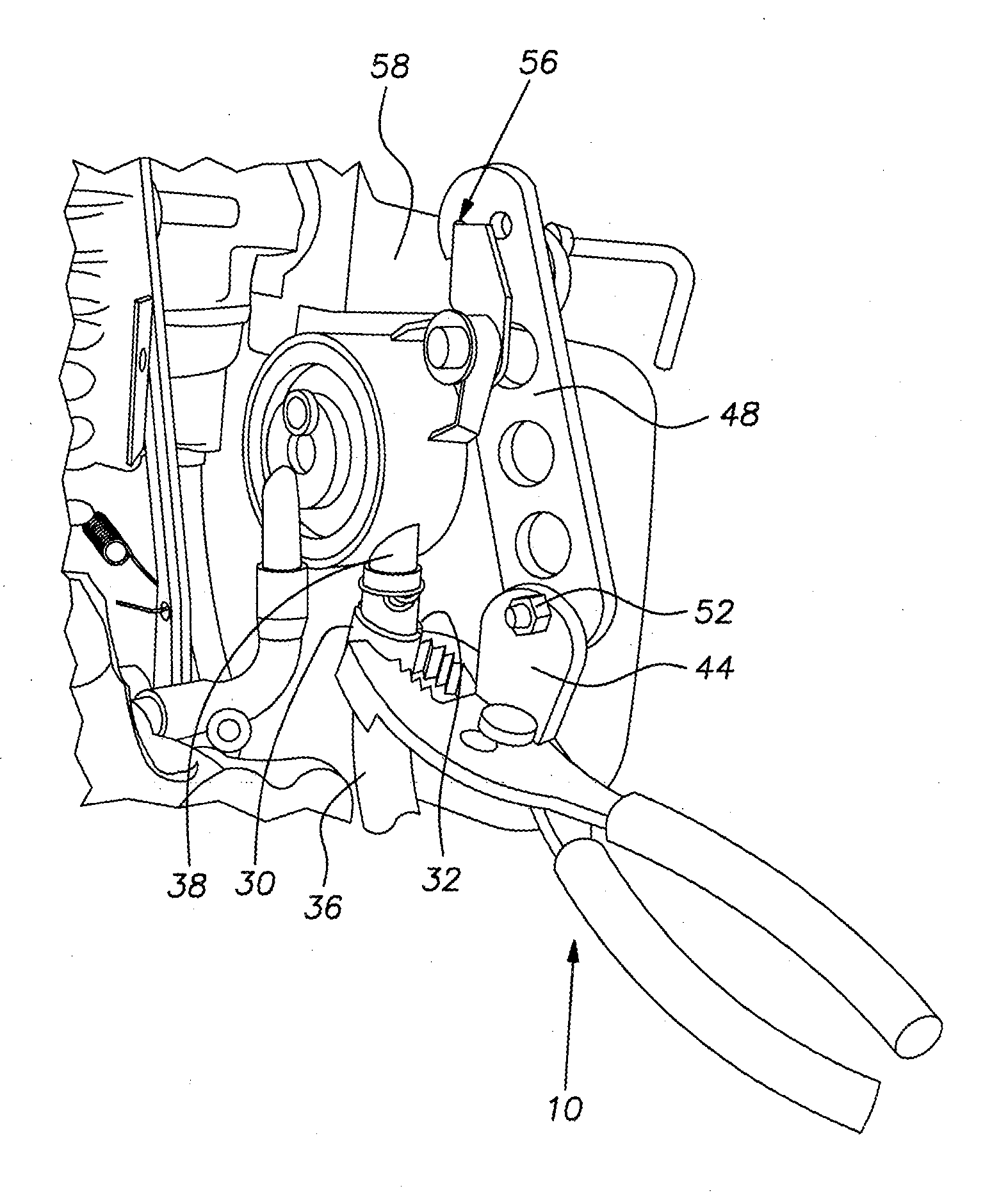
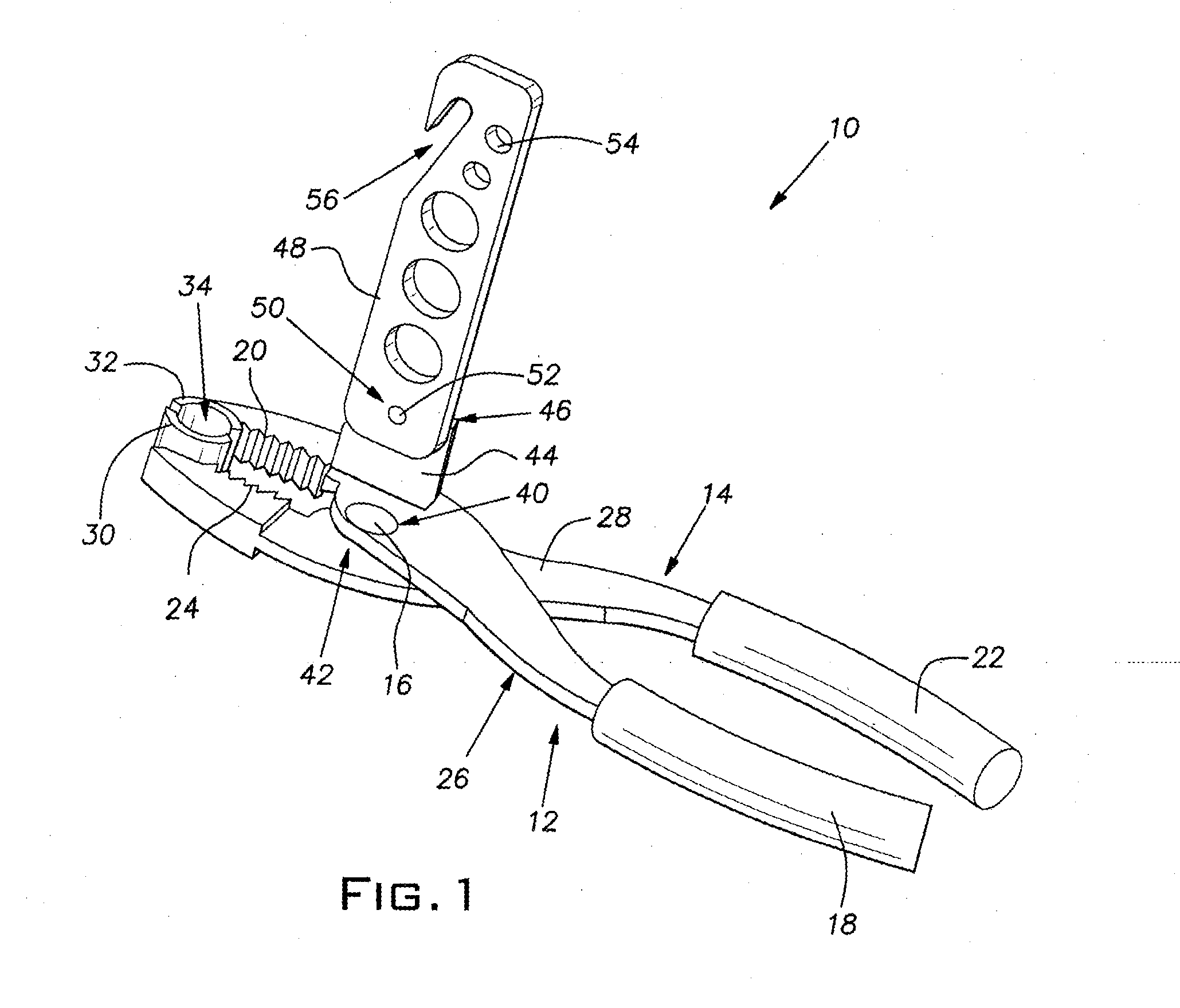
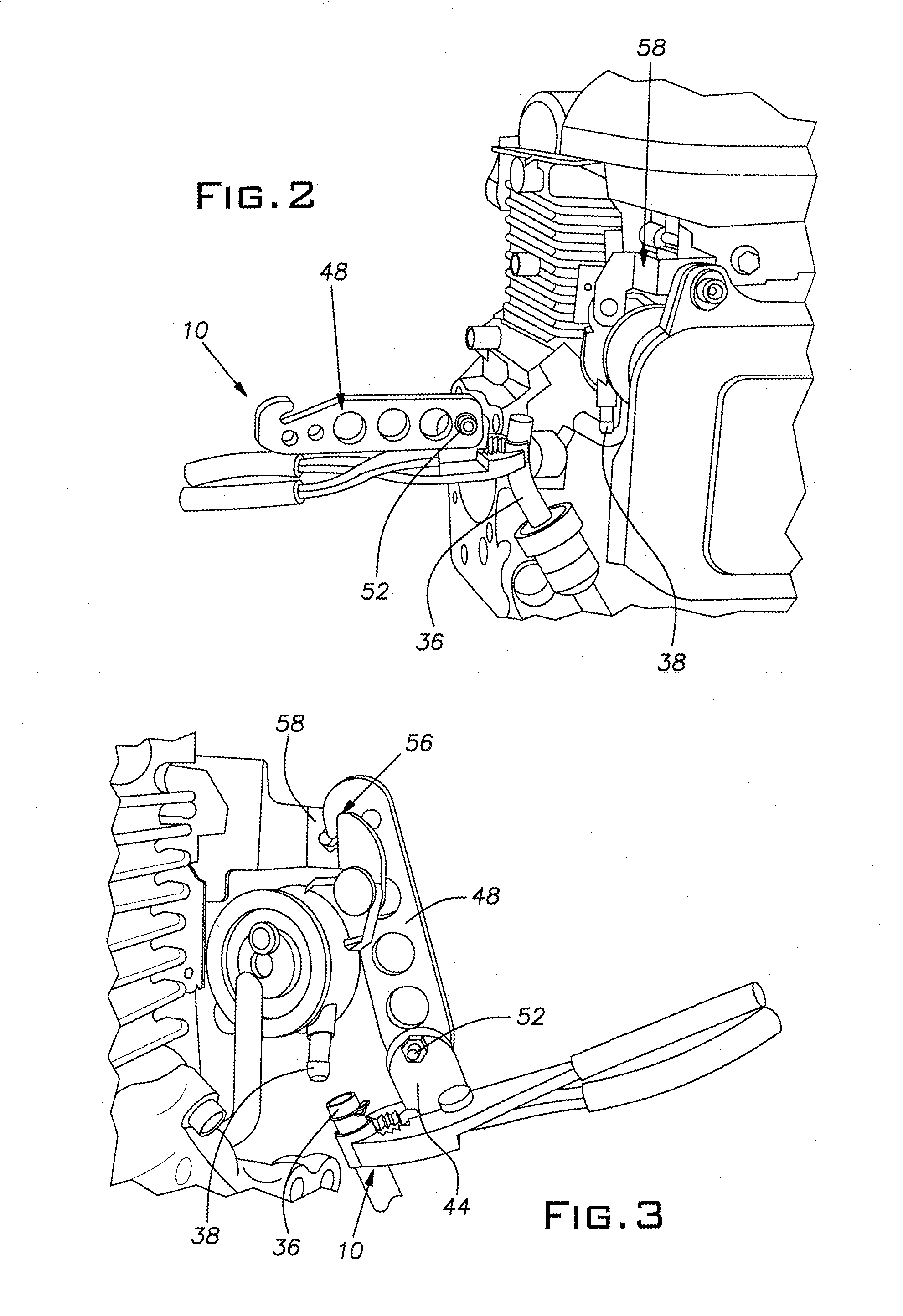
[0016]As shown in FIGS. 1-4, with particular attention to FIG. 1, a tool 10 of the present invention has first and second arms 12, 14 that are joined by a rivet 16. The first arm 12 has a first handle 18 and a first jaw surface 20, and the second arm 14 has a second handle 22 and a second jaw surface 24. The handles 18, 22 of the arms 12, 14 may be covered with a shock absorbing material to increase user comfort. The first and second arms 12, 14 each have an interior surface 26, 28. The inner surfaces 26, 28 of the first and second arms 12, 14 are generally perpendicular to the first and second jaw surfaces 20, 24, respectively. The first and second arms 12, 14 are of the same or similar shape and structure and are assembled so that their inner surfaces 26, 28 face each other. First and second grips 30, 32 are attached to the first and second jaw surfaces 20, 24, respectively. Each of the grips 30, 32 have knurls 34 for gripping a tube 36 for installation on a barb 38, as shown in F...


PUM

PropertyMeasurementUnit
leverage forceaaaaaaaaaa
outer diameteraaaaaaaaaa
inner diameteraaaaaaaaaa

Abstract

A fuel insertion tube tool for installing a fuel tube on a barb. The tool has first and second arms that are pivotably attached through an arm pivot axis. Each arm has a grip to engage the fuel tube. A tab extends from the first arm and is pivotably attached to a proximal end of a bar with a pivot pin that defines a bar axis. The bar axis and the arm axis are perpendicular to each other. A hook is disposed at a distal end of the bar for engagement with an attachment site. The tab functions as a fulcrum to reduce the amount of force required to install the fuel tube on the barb. The bar has weight reducing holes and the grips have straight knurls for frictional engagement with the fuel tube.

Description

[0001]This application is a divisional of U.S. application Ser. No. 12 / 043,451 filed on Mar. 6, 2008, which is expressly incorporated herein by reference.BACKGROUND OF THE INVENTION[0002]1. Field of the Invention[0003]The presently disclosed embodiments are directed to the field of hand tools. In particular, the present invention relates to a method and apparatus for installing fuel tubes.[0004]2. Description of Related Art[0005]Many products, specifically internal combustion engines, utilize tubes, lines, or hoses to communicate fluid between different locations. The fluid may be for use in for example, cooling, fueling, hydraulic, lubricating, and vacuum operations. For example, a fuel tube is used to transport fuel between a fuel tank, a fuel pump, and a carburetor of the engine. Alternatively, a radiator hose is used to transport engine coolant between the cooling channels of the engine and the radiator.[0006]Traditionally, at each of the different locations, whether they be the...

Claims


Application Information

Patent Timeline
Patent Type & Authority Applications(United States)
IPC IPC(8): B23P19/02B23P19/12
CPCB25B7/00B25B7/02B25B7/22Y10T29/49945Y10T29/5367Y10T29/49895Y10T29/4987Y10T29/49826
Inventor MARSHALL, CHAD
Owner HONDA MOTOR CO LTD
Learn More