Flow rate controller and proportional electromagnetic valve

a technology of flow rate controller and proportional electromagnetic valve, which is applied in the direction of valve operating means/release devices, process and machine control, etc., can solve the problems of deteriorating the life of proportional electromagnetic valve, the movement of the moving core is not smooth, etc., and achieves the effect of stably adjusting a relatively large flow rate of fluid

Active Publication Date: 2011-07-14
CKD
View PDF8 Cites 18 Cited by
  • Summary
  • Abstract
  • Description
  • Claims
  • Application Information

AI Technical Summary

Benefits of technology

[0015]According to the above configuration, it is possible to provide the flow rate cont...

Problems solved by technology

Due to sliding resistance, the movable core does not move smoothly.
Thus, abrasion powder is generated bet...

Method used


Image

  • Flow rate controller and proportional electromagnetic valve
  • Flow rate controller and proportional electromagnetic valve
  • Flow rate controller and proportional electromagnetic valve

Examples


Embodiment Construction

[0043]A detailed description of a preferred embodiment of a flow rate controller and a proportional electromagnetic valve embodying the present invention will now be given referring to the accompanying drawings.

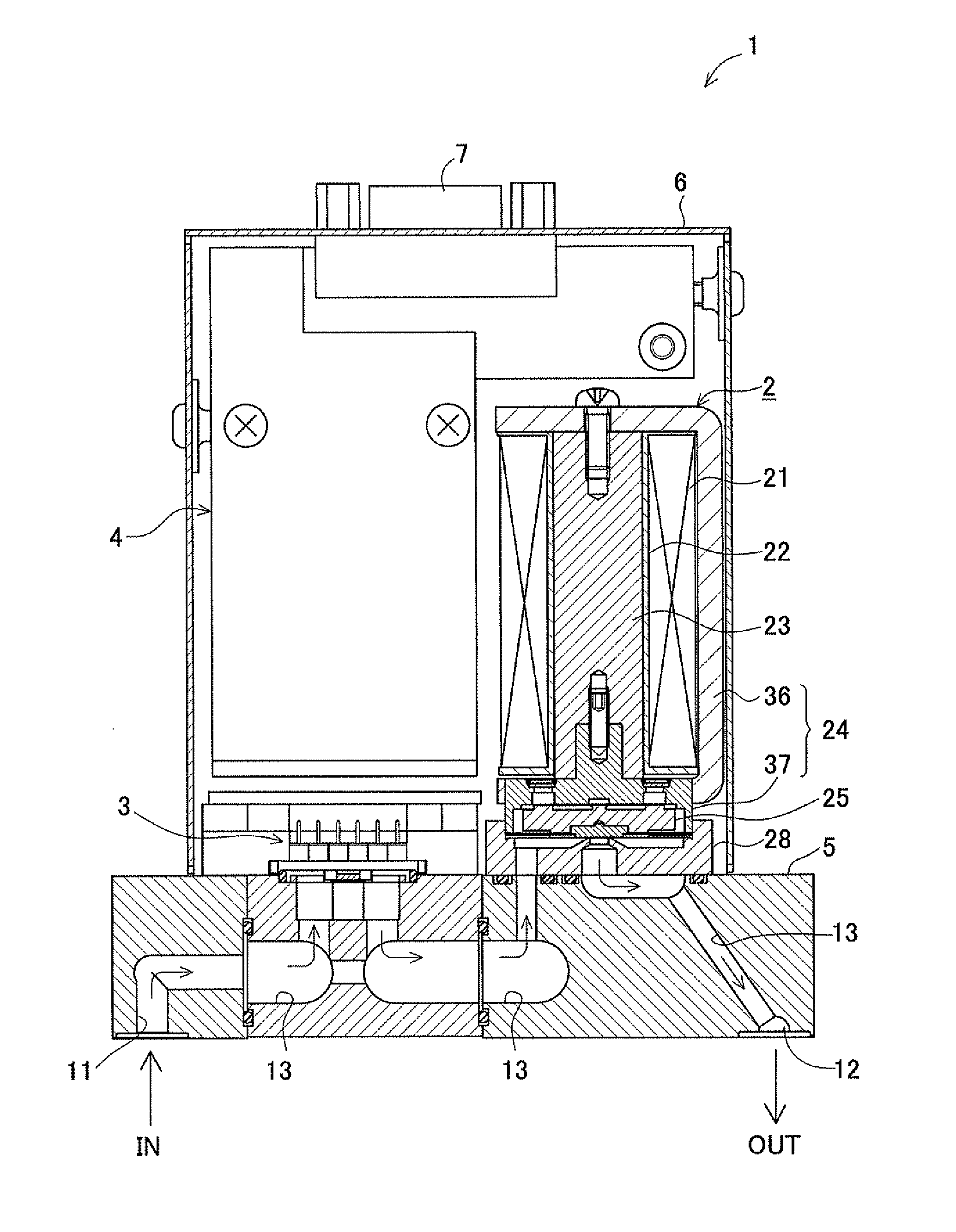
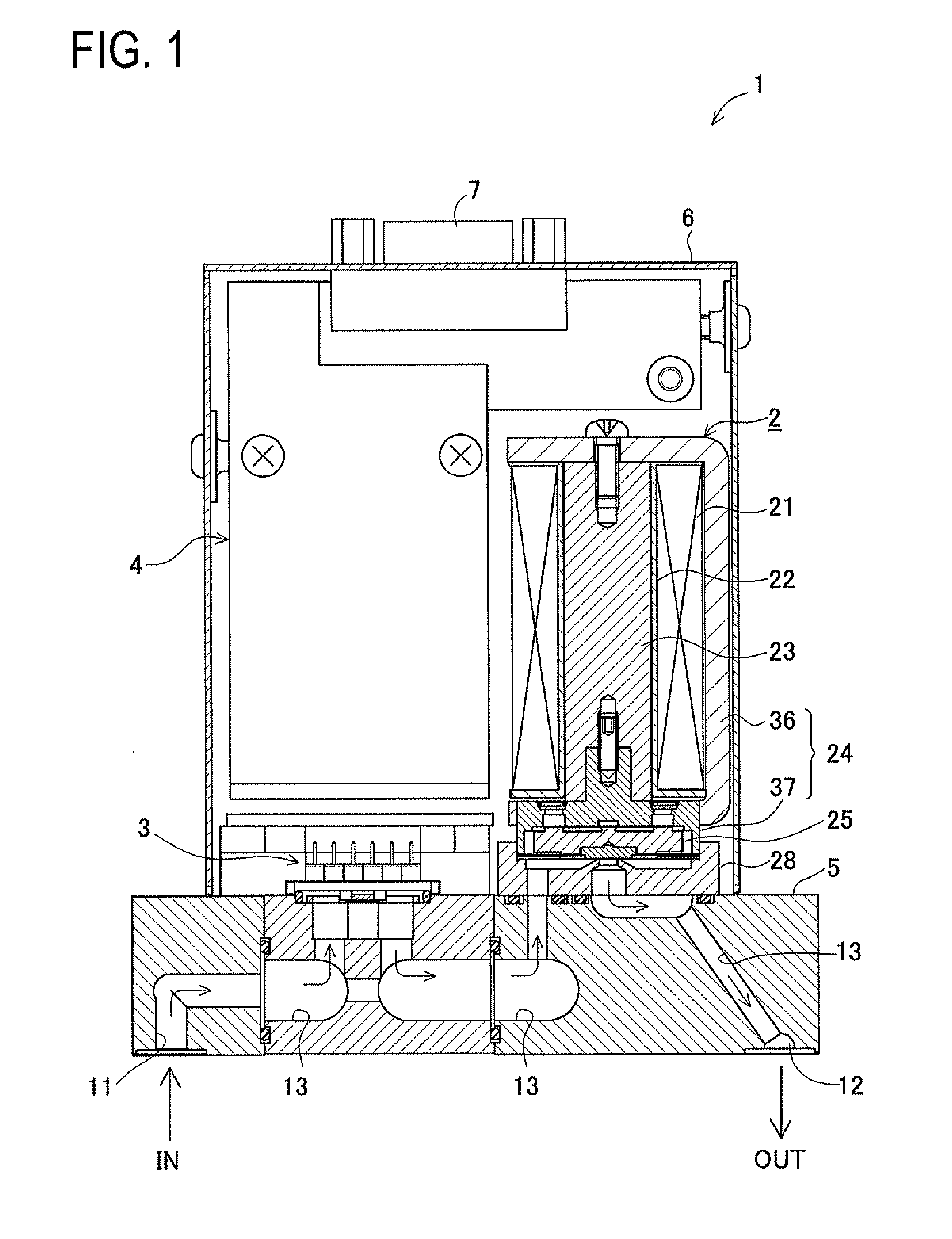
[0044]FIG. 1 is a cross sectional view of a flow rate controller 1 in this embodiment. This flow rate controller 1 includes a proportional electromagnetic valve 2 for adjusting the flow rate of a fluid, a flow rate sensor 3 for detecting the flow rate of the fluid, and a control circuit 4 for controlling the proportional electromagnetic valve 2 so that the flow rate detected by the flow rate sensor 3 reaches a predetermined target flow rate. The flow rate controller 1 further includes a base block 5 and a casing 6. The base block 5 is formed with an inlet 11, an outlet 12, and a flow path 13 (13a, 13b, 13c) located between the inlet 11 and the outlet 12. On the base block 5, the proportional electromagnetic valve 2 and the flow rate sensor 3 are fixedly mounted. The fluid ent...


PUM


Abstract

A flow rate controller is arranged such that a control circuit controls a proportional electromagnetic valve so that a flow rate detected by a flow rate sensor reaches a target flow rate. The proportional electromagnetic valve includes a coil supported in a holder, a bobbin and a fixed core, a valve element and a plate spring placed on a movable core, the valve seat, lead-in path, lead-out path, and orifice being formed in a body. The movable core is displaced by balance between an attractive force of the fixed core generated by excitation of the coil and an urging force of the plate spring, thereby adjusting the position of the valve element with respect to the valve seat to adjust the flow rate of a fluid. The orifice has an inside diameter set to a value of “φ1 mm or more” and an axial length set to a value to have a ratio of “from 0.1 to 0.6 inclusive” to the inside diameter. The lead-out path has an inside diameter set to be larger than the inside diameter of the orifice.

Description

CROSS-REFERENCE TO RELATED APPLICATIONS[0001]This application is based upon and claims the benefit of priority from the prior Japanese Patent Application No. 2010-004746, filed Jan. 13, 2010, the entire contents of which are incorporated herein by reference.TECHNICAL FIELD[0002]The present invention relates to a flow rate controller arranged to proportionally control the flow rate of a fluid and a proportional electromagnetic valve usable therein.BACKGROUND ART[0003]Heretofore, a technique of this type is known as a flow rate controller disclosed in JP 2007-206936A. This flow rate controller includes a proportional electromagnetic valve arranged to proportionally control the flow rate of a fluid, a flow rate sensor for detecting the flow rate of the fluid, and a control circuit for controlling the proportional electromagnetic valve so that a detection value of the flow rate sensor reaches a predetermined target flow rate.[0004]Herein, the proportional electromagnetic valve disclosed...

Claims


Application Information

Patent Timeline
IPC IPC(8): F16K31/02
CPCF16K1/42G05D7/0635F16K31/0655Y10T137/7761F16K31/06H01F7/16F16F1/32
Inventor NISHIMURA, YASUNORI
Owner CKD
Why Eureka
Try Eureka