
Tone correcting apparatus providing improved tone correction on image

a tone correction and tone technology, applied in image enhancement, color signal processing circuits, instruments, etc., can solve the problems of unnatural bright or dark face parts, deterioration of contrast between bright and dark faces, and limited effect of tone correction

Active Publication Date: 2011-07-14
CASIO COMPUTER CO LTD
View PDF19 Cites 13 Cited by
  • Summary
  • Abstract
  • Description
  • Claims
  • Application Information

AI Technical Summary

Benefits of technology

According to a second aspect of the present invention, there is provided a method for correcting a tone of an image, the method including: acquiring first brightness information indicating brightness of each of a plurality of block regions that are set to cover an entire area of the image; detecting a face portion where a human face is positioned in the image; acquiring second brightness information indicating brightness of the face portion; and correcting brightness of the image based on the first brightness information and the second brightness information.

Problems solved by technology

However, the conventional tone correction is designed for a general-purpose use, and its effect may be limited in some cases.
For example, in a case in which a human face exists in an image to be subjected to the tone correction, a contrast between a bright portion and a dark portion in the face portion tends to be deteriorated, and when a brightness of a face portion, where the human face is positioned, and a brightness of background portion largely differ from each other, the face portion becomes unnaturally bright or dark by the tone correction.
As described above, the conventional tone correction may not apply a favorable correction to the face portion.

Method used


Image

  • Tone correcting apparatus providing improved tone correction on image
  • Tone correcting apparatus providing improved tone correction on image
  • Tone correcting apparatus providing improved tone correction on image

Examples


first embodiment

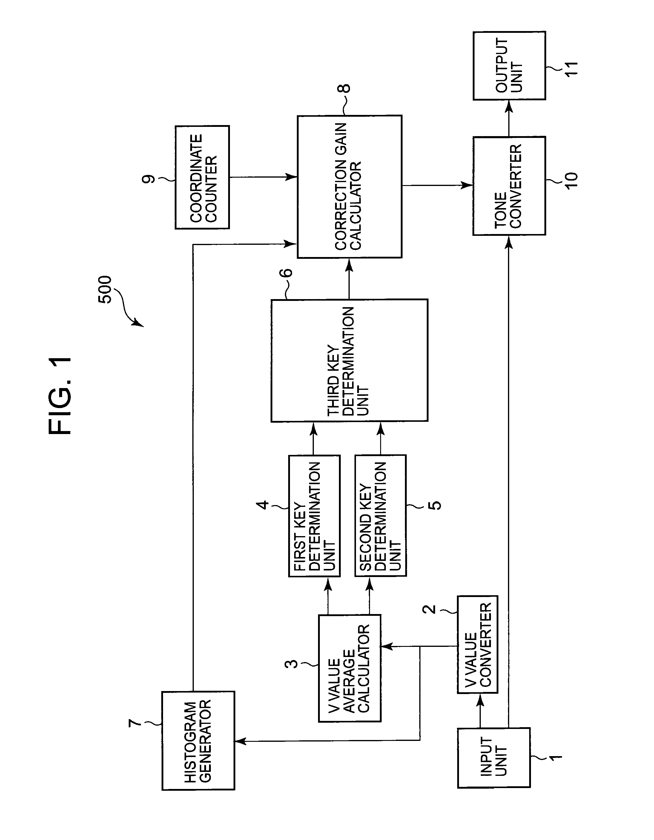
A first embodiment according to the present invention will be described below. FIG. 1 is a block diagram showing a configuration of a tone correcting apparatus 500 according to the first embodiment. The tone correcting apparatus 500 serves to automatically correct a tone of an input image. The tone correcting apparatus 500 is incorporated and utilized in an image capturing apparatus, such as a digital camera, and an image processing apparatus, such as a printer, which have various image processing functions.

As shown in FIG. 1, the tone correcting apparatus 500 includes: an input unit 1 for inputting image data including pixel data for each of color components of R, G and B; a V value converter 2; a V value average calculator 3; a first key determination unit 4; a second key determination unit 5; a third key determination unit 6; a histogram generator 7; a correction gain calculator 8; a coordinate counter 9; a tone converter 10; and an output unit 11. The tone converter 10 adjusts, ...

second embodiment

A second embodiment according to the present invention will be described below. In the following description of the second embodiment, identical or equivalent components and operations to those in the first embodiment will be described by using the same reference numerals as those in the first embodiment with reference to the drawings used in the description of the first embodiment.

FIG. 11 is a block diagram showing a configuration of a tone correcting apparatus 600 according to the second embodiment. The tone correcting apparatus 600 automatically corrects a tone of an input image. The tone correcting apparatus 600 is incorporated and utilized in an imaging device such as a digital camera, a printer or various image processing apparatuses having various image processing functions.

As shown in FIG. 11, the tone correcting apparatus 600 includes: an input unit 601 for inputting image data including pixel data for each of color components of R, G and B; a V value converter 602; a V val...


PUM


Abstract

A tone correcting apparatus includes: a first acquiring unit that acquires first brightness information indicating brightness of each of a plurality of block regions that are set to cover an entire area of an image; a face detecting unit that detects a face portion where a human face is positioned in the image; a second acquiring unit that acquires second brightness information indicating brightness of the face portion detected by the face detecting unit; and a correction unit that corrects brightness of the image based on the first brightness information and the second brightness information.

Description

TECHNICAL FIELDThe present invention relates to a tone correcting apparatus, a method for correcting a tone of an image, and a computer-readable storage medium containing a sequence of instructions for a program executable by a computer for correcting a tone of an image, which are suitable to be utilized in an image processing apparatus, such as a digital camera.BACKGROUNDConventionally, as a method of automatically correcting atone of an image, there has been a method in which a brightness level of an image is corrected for each of pixels included in the image. An example of such method is described in JP-A-9-065252 (counterpart U.S. Pat. No. 5,808,697). In the method, an input image is divided into a plurality of block regions, and an average brightness level (an average of brightness levels of all pixels) is obtained for each of the block regions. Next, a correction curve is independently selected for each of the block regions corresponding to the average brightness level. Next, ...

Claims


Application Information

Patent Timeline
IPC IPC(8): G06T5/00
CPCH04N5/2351H04N5/23219H04N23/611H04N23/71G06T5/00H04N5/20H04N9/68H04N5/66
Inventor MANABE, YOSHITSUGU
Owner CASIO COMPUTER CO LTD
Learn More