Underrun prevention member for vehicle bumper beam

a technology for preventing members and bumper beams, which is applied to bumpers, superstructure subunits, roofs, etc., can solve the problems of increasing the manufacture cost of devices, affecting the safety of vehicles, so as to achieve the effect of preventing further underrun, reducing the manufacturing cost of devices, and increasing the stiffness of underrun prevention members

Inactive Publication Date: 2011-07-21
TOYODA IRON WORKS CO LTD
View PDF4 Cites 7 Cited by
  • Summary
  • Abstract
  • Description
  • Claims
  • Application Information

AI Technical Summary

Benefits of technology

[0011]The above underrun prevention member for a vehicle bumper beam includes the vertical plate portion that is integrally fixed to the outer side wall of the bumper beam; the reinforcement plate portion that is integrally provided to be continuous with the protruded end of the vertical plate portion; and the paired side plate portions that are integrally provided to be continuous with both ends of the reinforcement plate portion in the vehicle widthwise direction, and are integrally fixed to the horizontal walls of the bumper beam. Then, the underrun under an object outside the vehicle or the object outside the vehicle under the bumper beam is prevented by the vertical plate portion that protrudes in the top-bottom direction beyond the horizontal walls. The reinforcement plate portion, which extends from the vertical plate portion toward the inside of the vehicle, is provided at the protruded end of the vertical plate portion. Thus, stiffness of the underrun prevention member is increased. In addition, the paired side plate portions provided at the both ends of the reinforcement plate portion are integrally fixed to the horizontal wall of the bumper beam, respectively. Thus, deformation of the vertical plate portion and the reinforcement plate portion is suppressed, and an underrun is further appropriately prevented. In this case, the reinforcement plate portion is shorter than the horizontal walls. Thus, when the bumper beam is deformed toward the inside of the vehicle, there is a low possibility that the reinforcement plate portion enters the inside of the vehicle beyond the bumper beam and then interferes with the vehicle component, such as a radiator, to damage the vehicle component.
[0012]In addition, the underrun prevention member, which includes the vertical plate portion, the reinforcement plate portion, and the paired side plate portions, is easily formed by subjecting a sheet of metal plate material to bending, drawing, or the like, through pressing. Thus, the underrun prevention member is easily manufactured at low cost as compared with the device described in JP-A-2009-1199 in which the portions are overlapped with each other and connected to each other.
[0013]In addition, in the second aspect of the invention, each of the paired side plate portions includes the lateral inclined portion and the close contact portion, and each close contact portion is integrally fixed to the horizontal wall of the bumper beam. Thus, the fixing strength of the side plate portions fixed to the bumper beam is increased, then the stiffness of the underrun prevention member is increased, and the underrun prevention member is tightly fixed to the bumper beam. This makes it possible to further appropriately prevent an underrun.
[0014]In addition, in the third aspect of the invention, the vertical plate portion has a length in the vehicle widthwise direction such that the vertical plate portion reaches the outer edges of the paired side plate portions, and is integrally connected to the reinforcement plate portion and the paired side plate portions over the entire length of the vertical plate portion in the vehicle widthwise direction, so that the underrun prevention member has a substantially L-shaped cross section over the entire length of the underrun prevention member in the vehicle widthwise direction. Therefore, the stiffness of the underrun prevention member is increased, and the underrun of the bumper beam under an object outside the vehicle or the object outside the vehicle under the bumper beam is further appropriately prevented. In addition, the paired side plate portions are inclined so as to gradually approach the horizontal wall. Thus, press workability is improved. The underrun prevention member is integrally formed by subjecting a sheet of metal plate material to press forming (drawing or the like) entirely. Thus, the underrun prevention member 10 is easily manufactured at low cost.

Problems solved by technology

However, the device described in the publication No. 2009-1199 has a complicated structure, so it is necessary for any portions of the device to be bent, overlapped with each other and connected to each other in the device.
Thus, manufacturing cost of the device is increased.
In the device described in the publication No. 2003-252134, if the bumper beam is deformed toward the inside of the vehicle due to a collision, a protruded end of the underrun prevention member may enter the inside of the vehicle beyond the bumper beam (refer to FIG. 2B), and there may be a high possibility that the underrun prevention member interferes with a vehicle component, such as a radiator, to damage the vehicle component.

Method used


Image

  • Underrun prevention member for vehicle bumper beam
  • Underrun prevention member for vehicle bumper beam
  • Underrun prevention member for vehicle bumper beam

Examples


embodiments

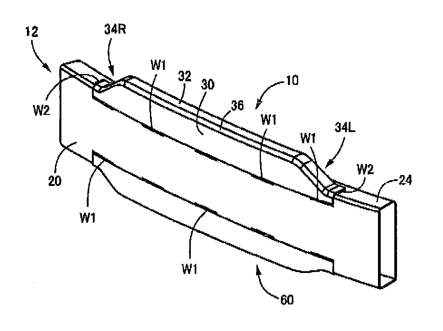
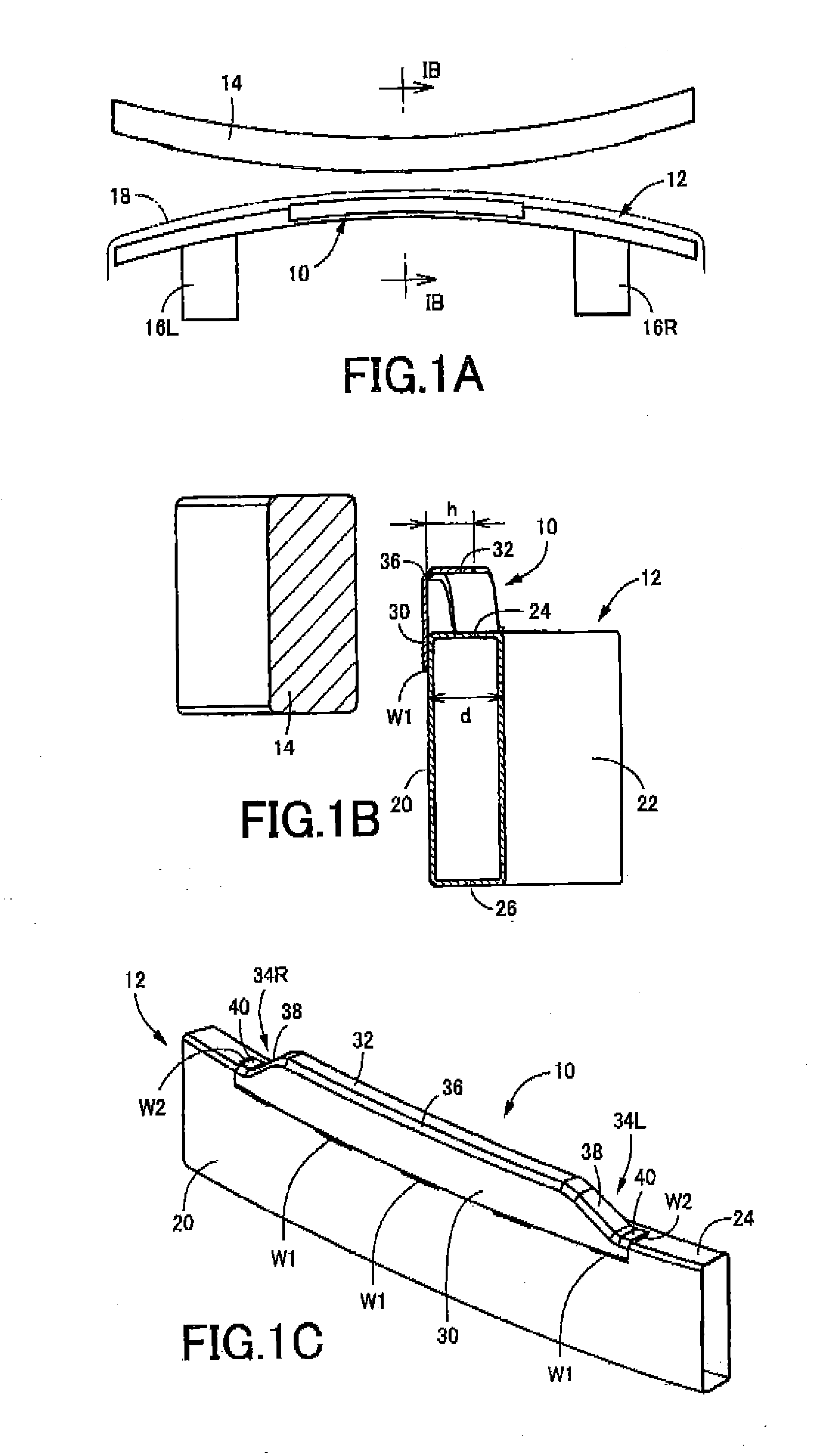
[0030]Hereafter, embodiments of the invention will be described in detail with reference to the accompanying drawings. FIG. 1A to FIG. 1C are views that illustrate a case where an underrun prevention member 10 is attached to a bumper beam 12 provided at the front portion of a vehicle, according to an embodiment of the invention. FIG. 1A is a plan view that shows the bumper beam 12 together with a barrier (collision object) 14, FIG. 1B is an enlarged cross-sectional view taken along the line IB-IB in FIG. 1A, and FIG. 1C is a perspective view of a center portion of the bumper beam 12, seen from a position diagonally ahead of and above the center portion, to which the underrun prevention member 10 is attached. The bumper beam 12 is integrally fixed to the front end portions of left and right side members 16L and 16R at positions near both left and right end portions of the bumper beam 12 via crash boxes (not shown) or the like, by bolts or the like. The bumper beam 12 is disposed in a...


PUM


Abstract

An underrun prevention member for a vehicle bumper beam including a substantially vertical outer side wall faced an area outside the vehicle and a horizontal wall provided so as to be extended substantially horizontally from an end of the outer side wall in a top-bottom direction toward an inside of the vehicle, disposed at a front portion or a rear portion of the vehicle so as to be extended substantially horizontally in a vehicle widthwise direction, and integrally fixed to the bumper beam so as to protrude in the top-bottom direction beyond the horizontal wall to prevent an underrun of the bumper beam under an object outside the vehicle or the object outside the vehicle under the bumper beam, the underrun prevention member includes: a vertical plate portion integrally fixed to the outer side wall so as to be in surface contact with the outer side wall, protruding in the top-bottom direction beyond the horizontal wall by a predetermined protrusion length, and having a predetermined width in the vehicle widthwise direction; a reinforcement plate portion integrally provided to be continuous with a protruded end of the vertical plate portion, extending from the protruded end toward the inside of the vehicle so as to be bent at an angle in the underrun prevention member, and having a length thereof in a vehicle front-rear direction being shorter than a length of the horizontal wall in the vehicle front-rear direction; and paired side plate portions integrally provided to be continuous with both ends of the reinforcement plate portion in the vehicle widthwise direction extending from the both ends of the reinforcement plate portion toward outer sides in the vehicle widthwise direction, inclined so as to gradually approach the horizontal wall respectively, and integrally fixed to the horizontal wall at an outer end portion thereof, respectively.

Description

INCORPORATION 3Y REFERENCE[0001]The disclosure of Japanese Patent Application No. 2010-009506 filed on Jan. 19, 2010 including the specification, drawings and abstract is incorporated herein by reference in its entirety.BACKGROUND OF THE INVENTION[0002]1. Field of the Invention[0003]The invention relates to a vehicle bumper beam and, more particularly, to an underrun prevention member that prevents occurrence of a situation where a bumper beam underruns a collision object or the collision object underruns the bumper beam to damage a vehicle component, such as a radiator.[0004]2. Description of the Related Art[0005]A bumper beam (also called bumper reinforcement) is widely used. The bumper beam is disposed at the front portion or the rear portion of a vehicle so as to extend substantially horizontally in a vehicle widthwise direction. The bumper beam may underrun a collision object or a collision object may underrun the bumper beam to damage a vehicle component, such as a radiator. T...

Claims


Application Information

Patent Timeline
Patent Type & Authority Applications(United States)
IPC IPC(8): B60R19/34
CPCB60R19/023B60R2019/186B60R19/18
Inventor KAMIYA, KEISUKE
Owner TOYODA IRON WORKS CO LTD
Why Eureka
Try Eureka