Multilayer antenna

a multi-layer antenna and antenna technology, applied in the direction of antennas, antenna details, electrical equipment, etc., can solve the problems of deterioration of reception sensitivity, disconnection of data communication, difficulty in obtaining the merits of mimo systems, etc., to reduce antenna size, increase channel capacity and data transfer rate, and intercept mutual interference

Inactive Publication Date: 2011-07-21
NEOPULSE
View PDF6 Cites 6 Cited by
  • Summary
  • Abstract
  • Description
  • Claims
  • Application Information

AI Technical Summary

Benefits of technology

[0019]Accordingly, it is an object of the present invention to provide a multilayer antenna with a plurality of adjacent antenna elements, which is capable of increasing channel capacity and data transfer rate by reducing an antenna size and intercepting mutual interference and noise between the antenna elements.

Problems solved by technology

However, as MIMO providing the above merits requires the plurality of antennas, for example, a mobile communication terminal requiring a plurality of antennas to be mounted in a space relatively smaller than a base station may produce an inter-antenna coupling effect that distorts or cancels out signals, which may result in deterioration of receipt sensitivity.
That is, in this case, a flow of induced current happens between the plurality of antennas and weakens signal sensitivity, which may result in disconnection of data communication and hence difficulty in obtaining the merits of MIMO system.
Examples of systems employing such a plurality of antennas include a tunable antenna system which selects and uses a plurality of antennas with different bands set, a smart antenna system having a configuration similar to that of MIMO, etc, but these systems still have the above-mentioned problems.
As shown, when monopole antennas are arranged adjacent to each other in a symmetrical manner, since an antenna signal at one antenna is induced in another adjacent antenna, thereby reducing antenna sensitivity, length of antenna is substantially reduced, which results in deterioration of communication performance.
It can be seen from this figure that, in the antenna array including two antenna elements, an antenna signal at one antenna element may be induced to another adjacent antenna element, but there is no means to prevent this effect.
In addition, an antenna gain is also reduced by any mutual signal interference, which results in decrease in channel capacity and data transfer rate.
However, the scheme of directly shorting the antennas has a critical problem of significant reduction of bandwidth due to change of band characteristics of the antennas, and the scheme of adding the signal processing circuit has a problem of difficulty in actual application due to complicated additional configuration.

Method used


Image

  • Multilayer antenna
  • Multilayer antenna
  • Multilayer antenna

Examples


Embodiment Construction

[0044]Hereinafter, a multilayer antenna according to preferred embodiments of the present invention will be described with reference to the accompanying drawings.

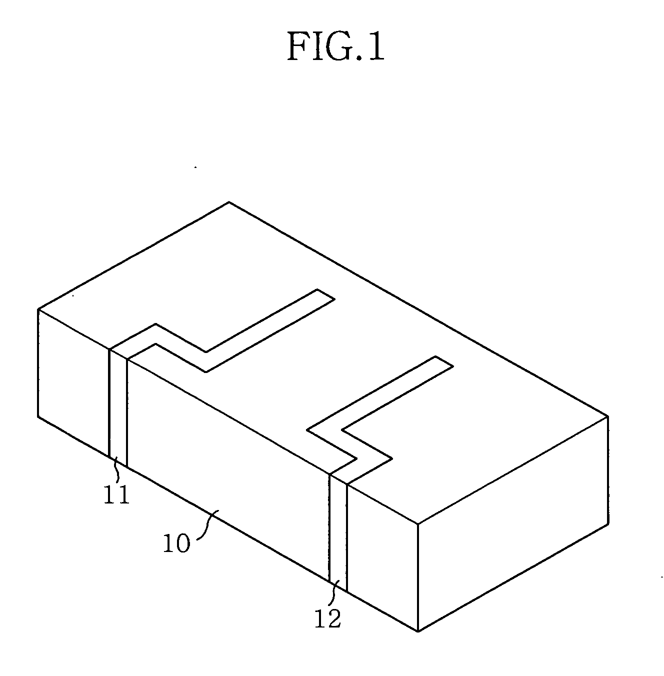
[0045]The embodiments to be shown below will be illustrated by way of example of MIMO (Multiple-Input, Multiple-Output) antenna, but may be applied to a smart antenna or the like having a structure similar to the MIMO antenna, or other antennas which are capable of reducing mutual interference between adjacent antenna elements.

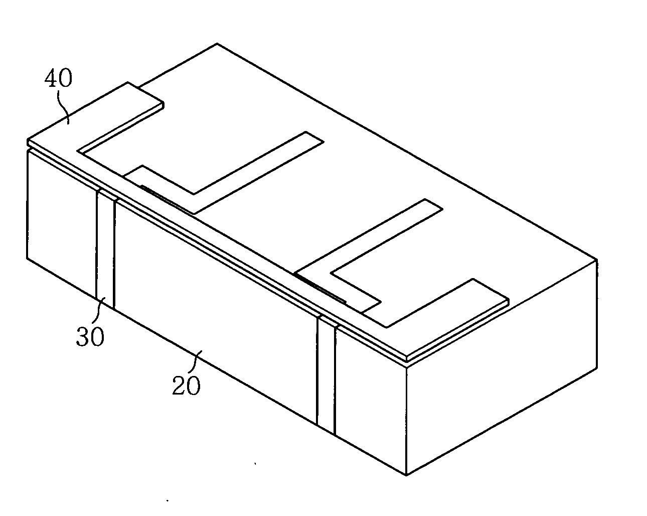
[0046]FIG. 4 is a perspective view of a multilayer antenna according to an embodiment of the present invention. As shown, a multi-layer monopole antenna system is constructed by arranging a pair of antenna strips 30 on a carrier 20 in the same way as the single layer monopole antenna system shown in FIG. 3 and placing an antenna plate 40 as an upper layer over the antenna strips 30, with an air layer formed between the antenna plate 40 and the antenna strips 30.

[0047]FIG. 5 is a sectional view of a po...


PUM


Abstract

The present invention relates to a multilayer antenna which is capable of improving communication performance by reducing an antenna size and increasing an antenna gain by improving performance of a plurality of antenna elements disposed adjacent to each other using a coupling. The multilayer antenna includes an antenna plate for coupling is arranged over plurality of antenna strips in a manner to be isolated from the antenna strips. With this configuration, the multilayer antenna is capable of increasing channel capacity and data transfer rate by reducing an antenna size and intercepting mutual interference and noise between the antenna elements.

Description

CROSS-REFERENCE TO RELATED APPLICATION[0001]This application claims the benefit of Korean Application No. 10-2008-0096234, filed on Sep. 30, 2008, and Korean Application No. 10-2008-0134807, filed on Dec. 26, 2008, with the Korean Intellectual Property Office, the disclosure of which is incorporated herein by reference.BACKGROUND OF THE INVENTION[0002]1. Field of the Invention[0003]The present invention relates to a multilayer antenna which is capable of improving communication performance by reducing an antenna size and increasing an antenna gain by improving performance of a plurality of antenna elements disposed adjacent to each other using a coupling.[0004]2. Description of the Related Art[0005]A wideband wireless communication system, such as WiMax, 802.11x, LTE(Long Term Evolution) and the like, which is catching on as the next generation communication system, has several problems which have to be solved to provide the same performance as or performance superior to wired voice...

Claims


Application Information

Patent Timeline
Patent Type & Authority Applications(United States)
IPC IPC(8): H01Q1/36H01Q21/00
CPCH01Q5/35H01Q5/378H01Q21/28H01Q1/521H01Q1/38H01Q5/0048H01Q5/0062
Inventor KIM, JUNG
Owner NEOPULSE
Why Eureka
Try Eureka