Tracking method and measuring system comprising a laser tracker

a tracking method and laser tracker technology, applied in the field of measuring technology, can solve the problem of not being able to evaluate the position of the target point with the help of the tracker

Active Publication Date: 2011-07-28
LEICA GEOSYSTEMS AG
View PDF6 Cites 52 Cited by
  • Summary
  • Abstract
  • Description
  • Claims
  • Application Information

AI Technical Summary

Benefits of technology

[0014]Methods known per se are applied for determining the direction to the target point from data recorded by the overview apparatus. If the overview apparatus is a camera, the target point may also be identified by way of a specific shape or color on the image recorded by the camera. This makes it possible to recognise and automatically select the target point from a plurality of elements simultaneously imaged by the camera, in a per se known manner. For cases in which the target point cannot be identified i

Problems solved by technology

The extraordinary tracking mode thus operates without the detection of the reflected measurement beam, and an evaluati

Method used


Image

  • Tracking method and measuring system comprising a laser tracker
  • Tracking method and measuring system comprising a laser tracker
  • Tracking method and measuring system comprising a laser tracker

Examples


Embodiment Construction

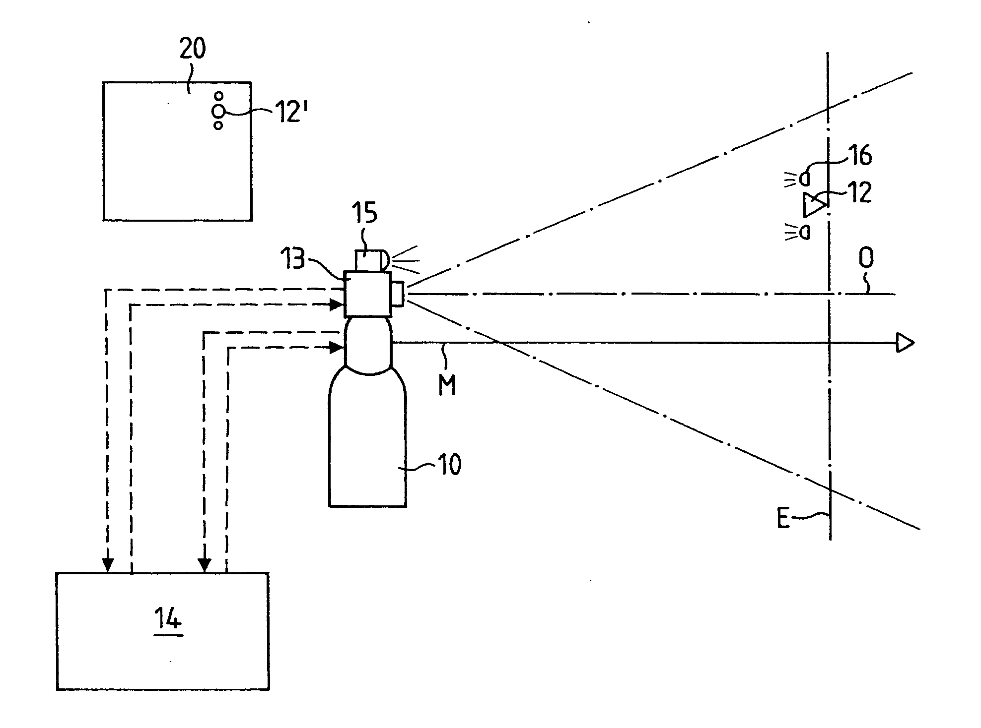
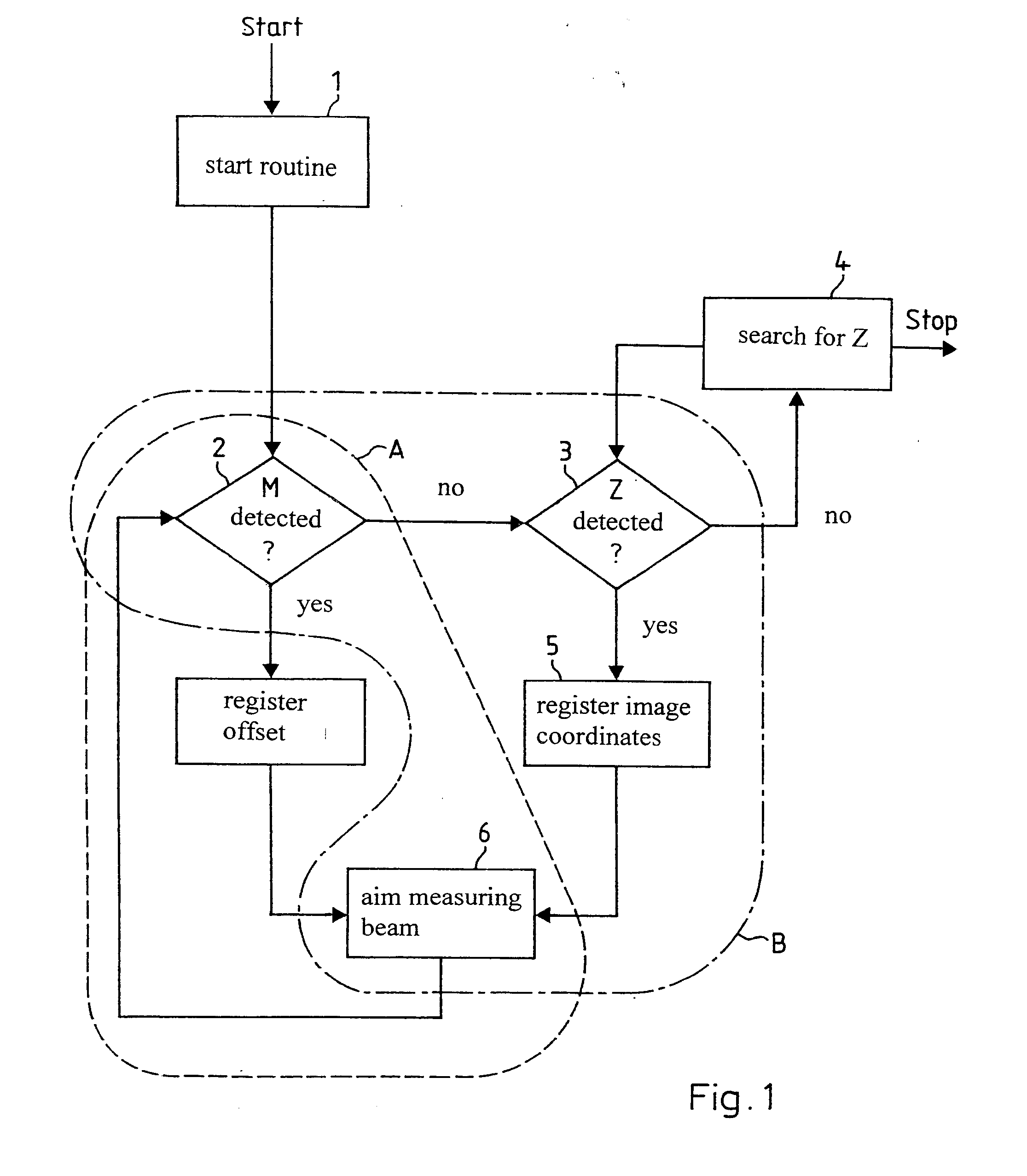
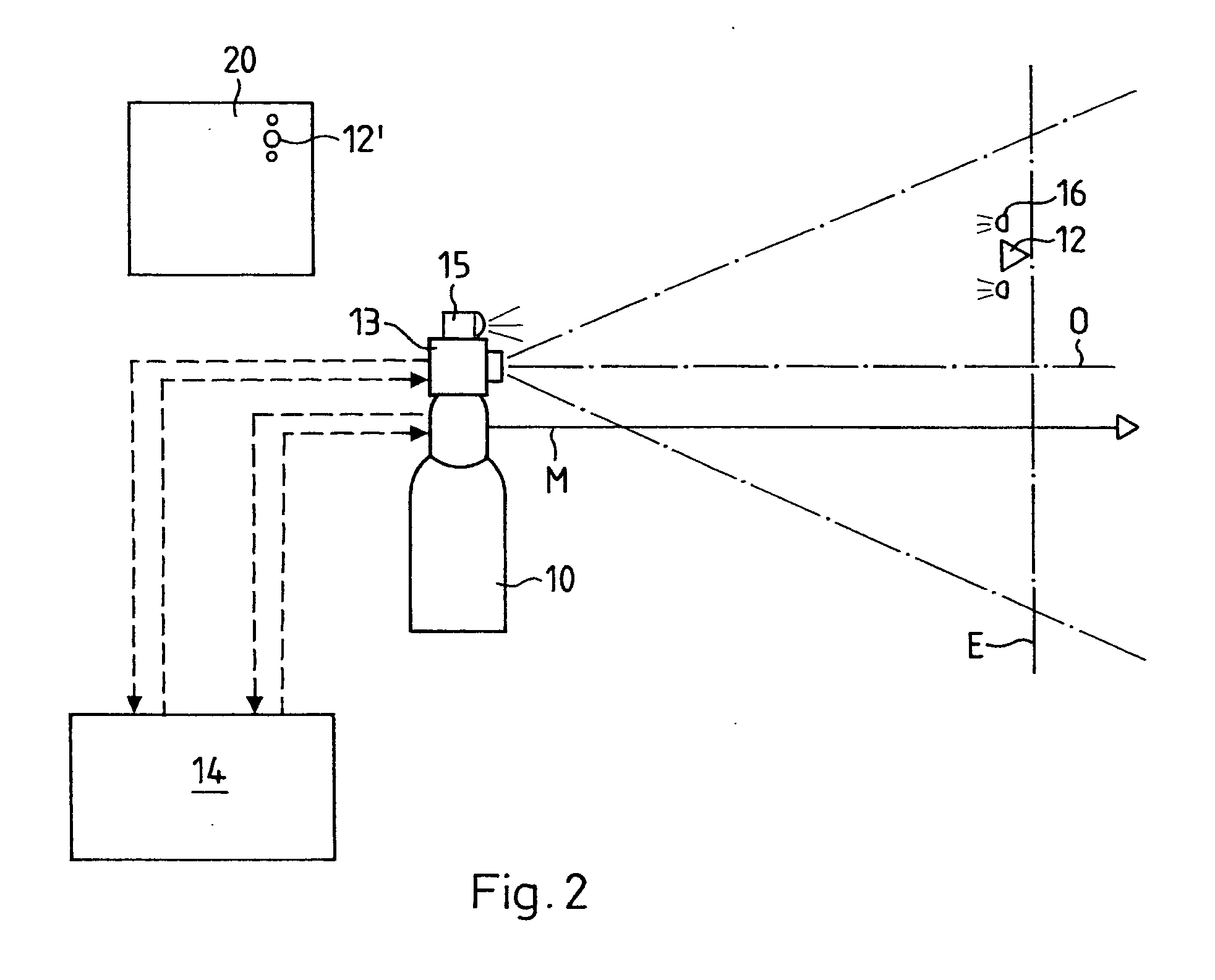
[0018]FIG. 1 is a block diagram of an exemplary embodiment of the tracking method according to the invention, wherein only the most important steps of the method are represented and wherein the overview apparatus is an overview camera.

[0019]After starting the system and after carrying out a start routine 1, which is determined by the system, and in which the system parts are activated, the system checks as to whether the measurement beam of the laser tracker, which may have any direction at the moment of the system start, is aimed at the target point, which may be positioned anywhere, or not. In other words, the system checks as to whether the laser tracker detects the reflected measurement beam or not (decision 2 with regard to the detection of the reflected measurement beam). If there is no reflected beam detection, the target point is looked for on the image provided by the overview camera. If the target point is not found on the image of the overview camera (decision 3 with rega...


PUM


Abstract

A measuring system includes a laser tracker (10), a target point marked by a reflector (12), a surveying apparatus (13), and an arithmetic and control unit (14). The laser tracker emits a measuring beam (M) which is reflected by the reflector, a process that is used for determining the distance between the laser tracker (10) and the reflector (12). The surveying apparatus has a known position and orientation relative to the measuring beam (M) while preferably being embodied as a survey camera. The inventive measuring system is designed so as to track the reflector (12) via the measuring beam (M). In a normal tracking mode (A), a measured value for controlling the orientation of the measuring beam (M) is derived from the detection of the measuring beam reflected by the reflector (12). If the measuring beam is not directed onto the reflector, the system switches to a special tracking mode in which the measured value for controlling the orientation of the measuring beam (M) is derived from an image (20) of the survey camera (13).

Description

BACKGROUND OF THE INVENTION[0001]The invention lies in the field of measurement technology and relates to a tracking method and to a measurement system with a laser tracker, according to the preambles of the respective patent claims. The tracking method serves for the automatic tracking of a target point, in particular a moving target point, with the aid of the measurement beam of a laser tracker. The measurement system with a laser tracker is designed for carrying out the method.[0002]So-called laser trackers are widely used for the measurement of the position of moving target points. A laser tracker is understood to be a device comprising at least one distance meter functioning with a focused laser beam (called measurement beam in the subsequent description). In such a laser tracker, for example, the direction of the measurement beam towards the target point is set with the help of a mirror rotatable about two axes, and is detected by an angle transmitter assigned to each one of t...

Claims


Application Information

Patent Timeline
IPC IPC(8): G01S17/66G01S17/86
CPCG01C15/002G01S17/66G01S17/023G01S17/86
Inventor DOLD, JURGENMOSER, DANIELZUMBRUNN, ROLAND
Owner LEICA GEOSYSTEMS AG
Why Eureka
Try Eureka