Load detecting device for roller bearing and roller bearing apparatus

Active Publication Date: 2011-07-28
JTEKT CORP
View PDF13 Cites 20 Cited by
  • Summary
  • Abstract
  • Description
  • Claims
  • Application Information

AI Technical Summary

Benefits of technology

[0007]It is an object of the invention to provide a load detecting device for a roller bearing and a roller bearing apparatus that are able

Problems solved by technology

On the other hand, a load applied to a bearing that supports a main shaft of a rotor has been increasing due to the upsizing of the generator, and, in addition, a

Method used


Image

  • Load detecting device for roller bearing and roller bearing apparatus
  • Load detecting device for roller bearing and roller bearing apparatus
  • Load detecting device for roller bearing and roller bearing apparatus

Examples


Embodiment Construction

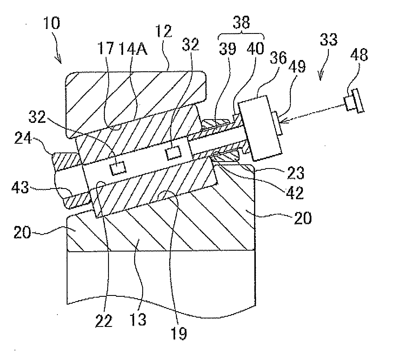
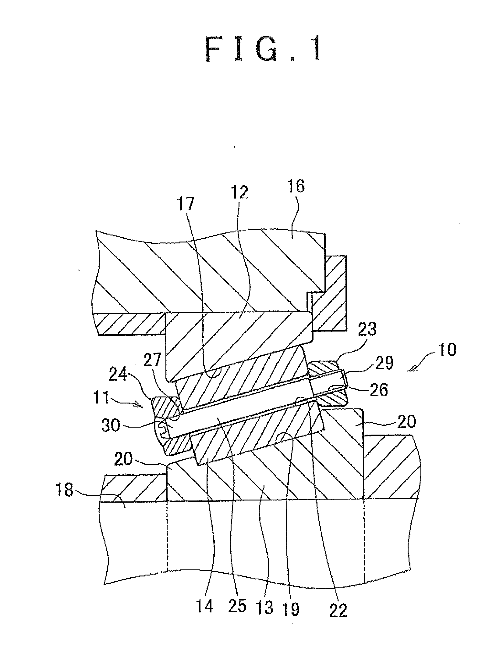
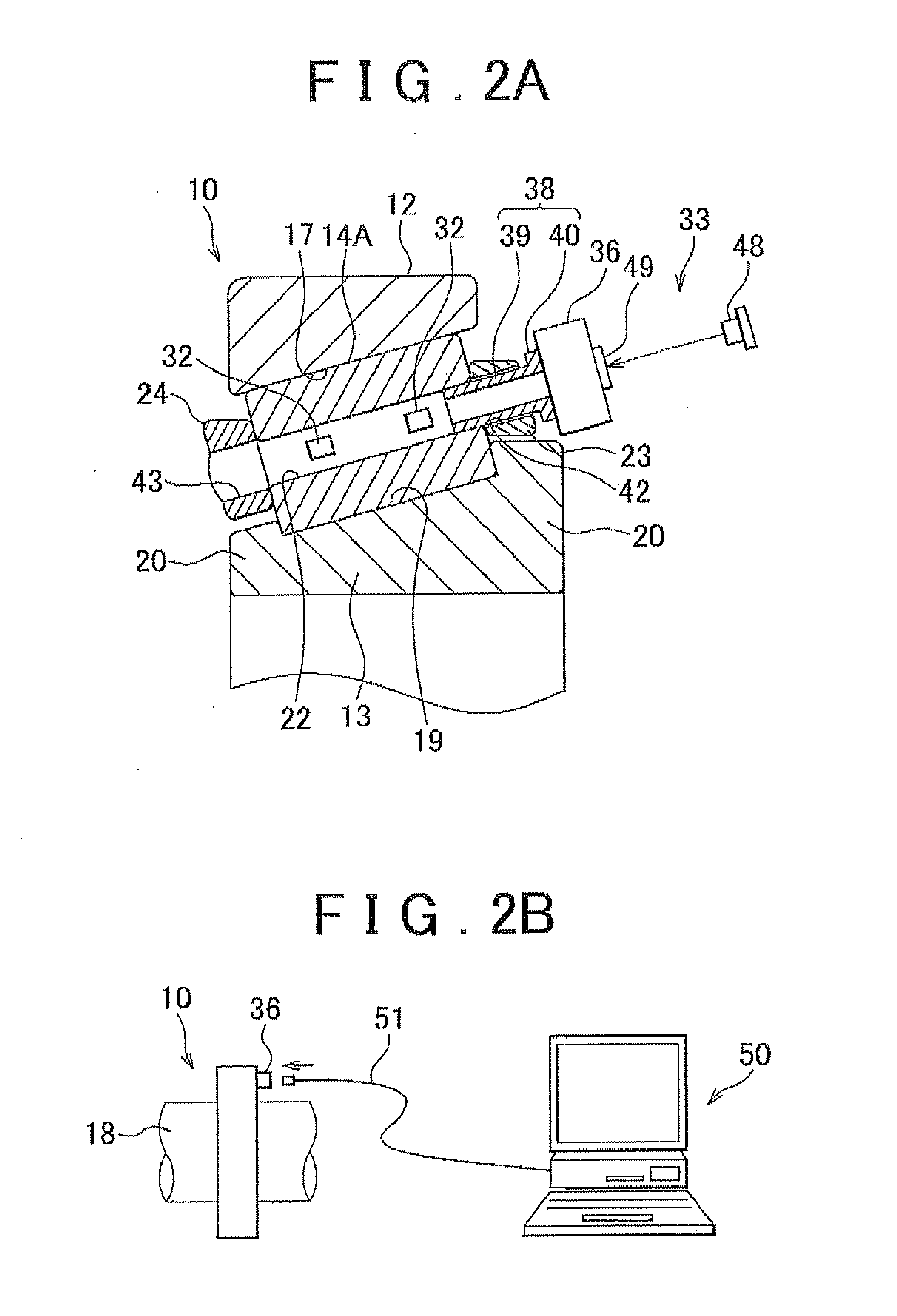
[0017]An embodiment of the invention will be described with reference to the accompanying drawings. FIG. 1 is a side sectional view of a tapered roller bearing 10 to which a load detecting device according to an embodiment of the invention is applied. The tapered roller bearing 10 according to the embodiment includes a pin-type retainer 11. The tapered roller bearing 10 includes an outer ring (a first bearing ring) 12, an inner ring (a second bearing ring) 13, a plurality of tapered rollers 14 and the pin-type retainer 11.

[0018]The outer peripheral side of the outer ring 12 is fixed to a housing 16. The outer ring 12 has an outer ring raceway surface 17 on its inner peripheral side. The outer ring raceway surface 17 is inclined with respect to the axial direction of the outer ring 12. In addition, the outer ring 12 is formed to have a trapezoidal sectional shape, that is, one axial end portion is formed so as to be thicker than the other axial end portion in the radial direction. In...


PUM


Abstract

A load detecting device for a roller bearing includes: a strain gauge that is provided in a roller arranged rollably between a first bearing ring and a second bearing ring and that detects a load applied to the roller; a position detecting sensor that detects a rotation position of the roller in a revolution direction of the roller; and a data logger that is provided for the roller and that records and stores a detection signal from the stain gauge.

Description

INCORPORATION BY REFERENCE[0001]The disclosure of Japanese Patent Application No. 2010-013215 filed on Jan. 25, 2010, including the specification, drawings and abstract, is incorporated herein by reference in its entirety.BACKGROUND OF THE INVENTION[0002]1. Field of the Invention[0003]The invention relates to a load detecting device for a roller bearing that is used to support, for example, a main shaft of a wind power generator, and a roller bearing apparatus.[0004]2. Description of the Related Art[0005]Wind, power generation becomes a focus of attention anew in recent years as an eco-friendly way to generate electric power without emitting carbon dioxide. Wind power generation has been rapidly becoming widespread in the world, while upsizing of a wind power generator has been proceeding in order to obtain a larger amount of generated power. In addition, in order to suppress an increase in the weight of a generator resulting from such upsizing, various structure improvements, such ...

Claims


Application Information

Patent Timeline
IPC IPC(8): F16C33/48F16C41/02
CPCF16C19/522F16C2300/14F16C33/523F16C33/34F16C19/364F16C33/526F16C41/008F16C2233/00
Inventor MATSUDA, SHINYATERAMOTO, TAKESHI
Owner JTEKT CORP
Why Eureka
Try Eureka