
Image misconvergence correction apparatus for less switching noise influence

a technology of switching noise and correction apparatus, which is applied in the field of image misconvergence correction apparatus, can solve the problems of large heat sink, high turn-on resistance and power consumption of power transistor, and malfunction of the correction value generator b>33/b>, and achieve the effect of less switching noise influen

Inactive Publication Date: 2007-01-02
SAMSUNG ELECTRONICS CO LTD
View PDF9 Cites 0 Cited by
  • Summary
  • Abstract
  • Description
  • Claims
  • Application Information

AI Technical Summary

Benefits of technology

[0024]The present invention has been devised to solve the above conventional problems, so it is an object of the present invention to provide a misconvergence correction apparatus and method for less switching noise influence.

Problems solved by technology

The power transistor has a drawback to high turn-on resistance and power consumption due to the nature of current-driven devices.
Accordingly, the operational amplifier having the A-, B-, or C-class amplification stage has a problem of a big heat sink to be provided due to the power consumption.
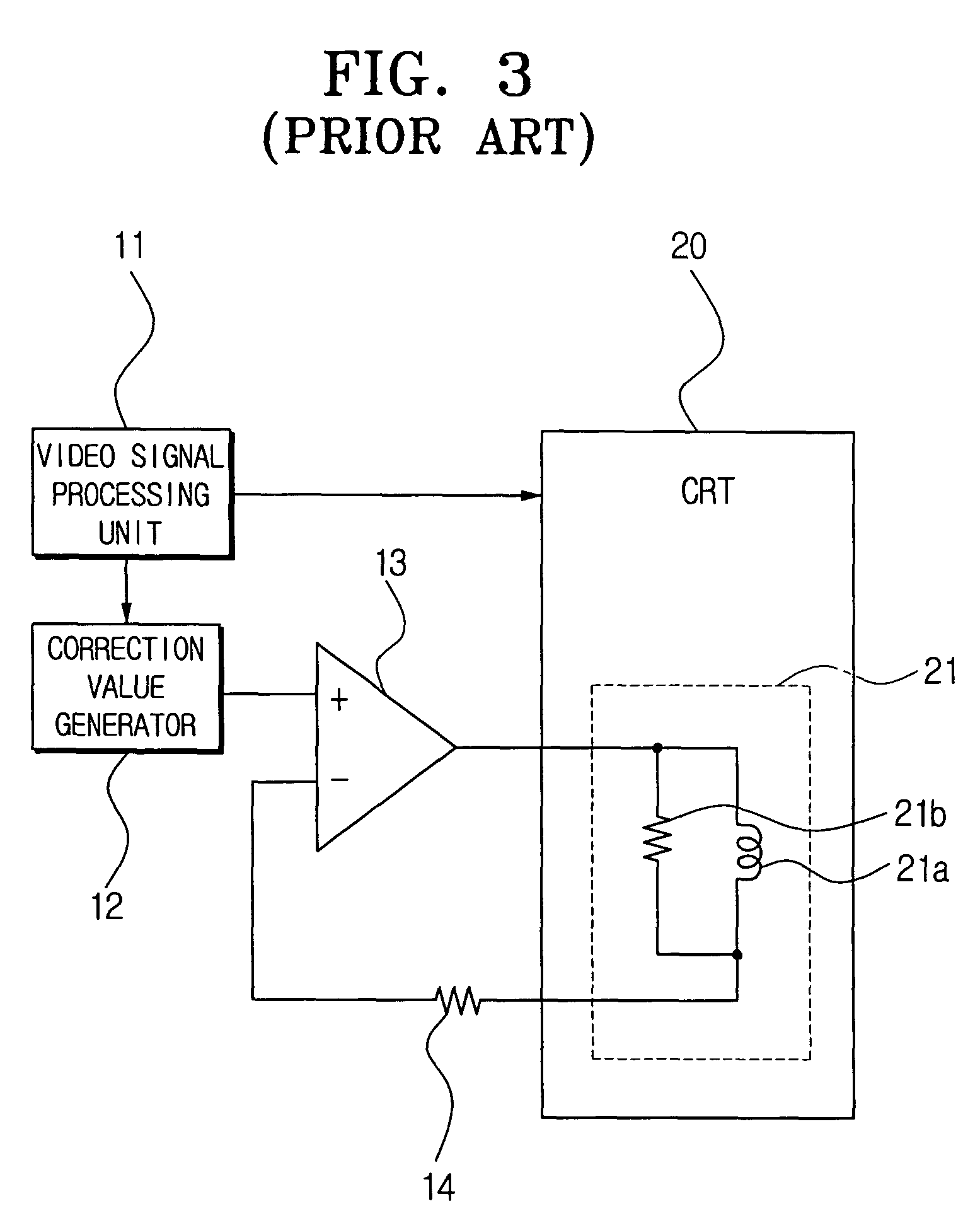
Therefore, the switching noise is fed back to the correction value generator 33, causing a problem that the correction value generator 33 is malfunctioned by the switching noise.

Method used


Image

  • Image misconvergence correction apparatus for less switching noise influence
  • Image misconvergence correction apparatus for less switching noise influence
  • Image misconvergence correction apparatus for less switching noise influence

Examples


Embodiment Construction

[0054]Hereinafter, the preferred embodiment of the present invention will be described in greater detail with reference to the accompanying drawings.

[0055]FIG. 7 is a conceptual block diagram for showing an image misconvergence correction apparatus according to an embodiment of the present invention.

[0056]The image misconvergence correction apparatus in FIG. 7 has a video signal processing unit 200, a correction value generator 300, a D-class amplifier 400, a low-pass filter (LPF) 500, a CRT 600, a convergence yoke 610, and a feedback sensor 700.

[0057]The video signal processing unit 200 processes a broadcast signal from an external source, and outputs a video signal, and vertical and horizontal synchronous signals. The video signal is transmitted to the CRT 600, and the vertical and horizontal synchronous signals are outputted to the correction value generator 300.

[0058]The correction value generator 300 is synchronized with the vertical and horizontal synchronous signals outputted...


PUM


Abstract

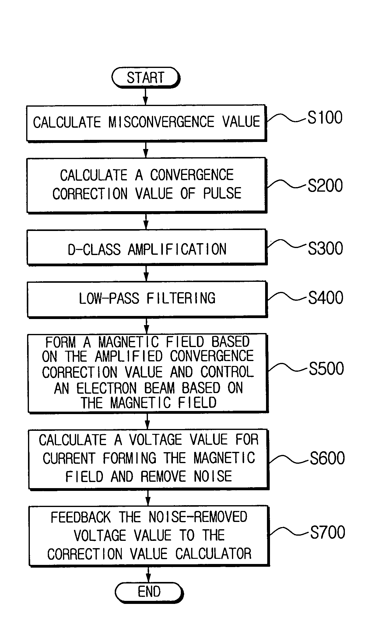
Disclosed is an image misconvergence correction apparatus having a correction value generation unit for calculating a convergence correction value to correct misconvergence occurring when a video signal is scanned on a display device; an amplification unit for performing D-class amplification with respect to the convergence correction value; a convergence yoke mounted in the display device to control a path of electron beams corresponding to the video signal based on the convergence correction value amplified in the amplification unit; and a feedback sensing unit for differentially amplifying a voltage value for electric current passing through the convergence yoke, and feeding back the differentially amplified voltage value to the correction value generation unit. The misconvergence correction apparatus amplifies and outputs a convergence correction value through the D-class amplifier having excellent power consumption and heat generation characteristics, calculates the convergence correction value, and minimizes influence of switching noise outputted from the D-class amplifier.

Description

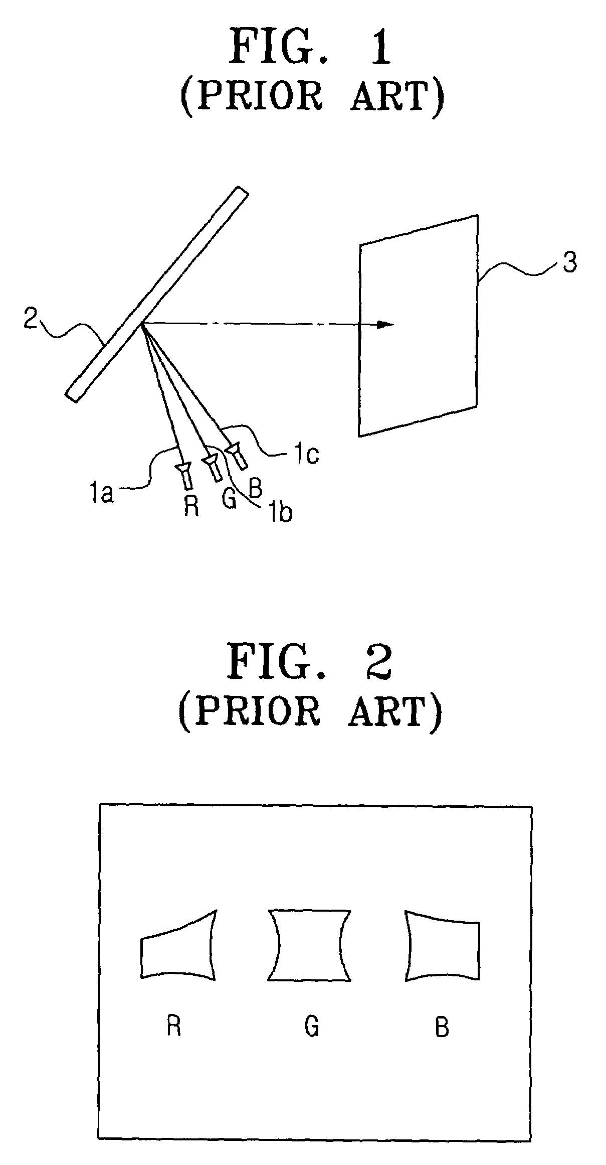
BACKGROUND OF THE INVENTION[0001]1. Field of the Invention[0002]The present invention relates to an image misconvergence correction apparatus for a projection television, and more particularly to an image misconvergence correction apparatus capable of correcting a video signal misconvergence. The present invention is based on Korean Patent Application No. 2002-40430, which is incorporated herein by reference.[0003]2. Description of the Prior Art[0004]In general, a television set scans red (R), blue (B), and green (G) beams from one electron gun on a display device of a cathode ray tube (CRT) to render images. Therefore, in the television set, only one electron gun is controlled for the image misconvergence correction.[0005]In the meantime, a projection television renders images through CRTs projecting images of the respective colors by the R, G, and B beams. The images projected through the respective CRTs are magnified, and the magnified images are reflected by mirror to be display...

Claims


Application Information

Patent Timeline
IPC IPC(8): H04N3/22H04N5/74H04N9/28H04N9/31
CPCH04N9/31H04N9/28
Inventor LEE, KYOUNG-GEUNROH, CHUNG-WOOKLEE, JOON-HWAN
Owner SAMSUNG ELECTRONICS CO LTD
Learn More