
Fuel cell stack

Active Publication Date: 2011-07-28
HONDA MOTOR CO LTD
View PDF4 Cites 4 Cited by
  • Summary
  • Abstract
  • Description
  • Claims
  • Application Information

AI Technical Summary

Benefits of technology

[0013]According to one aspect of the present invention, a fuel cell stack includes a plurality of unit cells stacked in a stacking direction substantially along a direction of gravity. Each of the plurality of unit cells includes a first metal separator, a second metal separator, a membrane electrode assembly, a reactant gas channel, a reactant gas inlet manifold, a reactant gas outlet manifold, and a bridge portion. The membrane electrode assembly is sandwiched between the first metal separator and the second metal separator. The membrane electrode assembly includes a first electrode, a second electrode, and an electrolyte membrane. The first electrode extends substantially in a horizontal direction. The second electrode extends substantially in the horizontal direction. The electrolyte membrane is sandwiched between the first electrode and the second electrode. The reactant gas channel allows a reactant gas to flow along a surface of each of the first and second metal separators. The reactant gas inlet manifold and the reactant gas outlet manifold allow the reactant gas to flow the reactant gas inlet manifold and the reactant gas outlet manifold in the stacking direction. The bridge portion forms a connection channel to connect at least the reactant gas outlet manifold to the reactant gas channel. The bridge portion includes a guide portion to break a continuity of condensed water.

Problems solved by technology

Such an internal manifold type fuel cell stack has a problem in that water, which is generated by a power generating reaction, may accumulate, in particular, near an outlet manifold (reactant gas outlet manifold).
In particular, if the separators are made of a metal, corrosion currents are easily generated on surfaces of the metal separators due to a potential difference.
As a result, the metal separators corrode and metal ions are emitted, which leads to a decrease in the performance of the electrolyte membrane.
Moreover, when the metal separator becomes thinner due to the corrosion, a hole may form in the metal separator, which leads to a decrease in gas shielding capability.

Method used


Image

  • Fuel cell stack
  • Fuel cell stack
  • Fuel cell stack

Examples


first embodiment

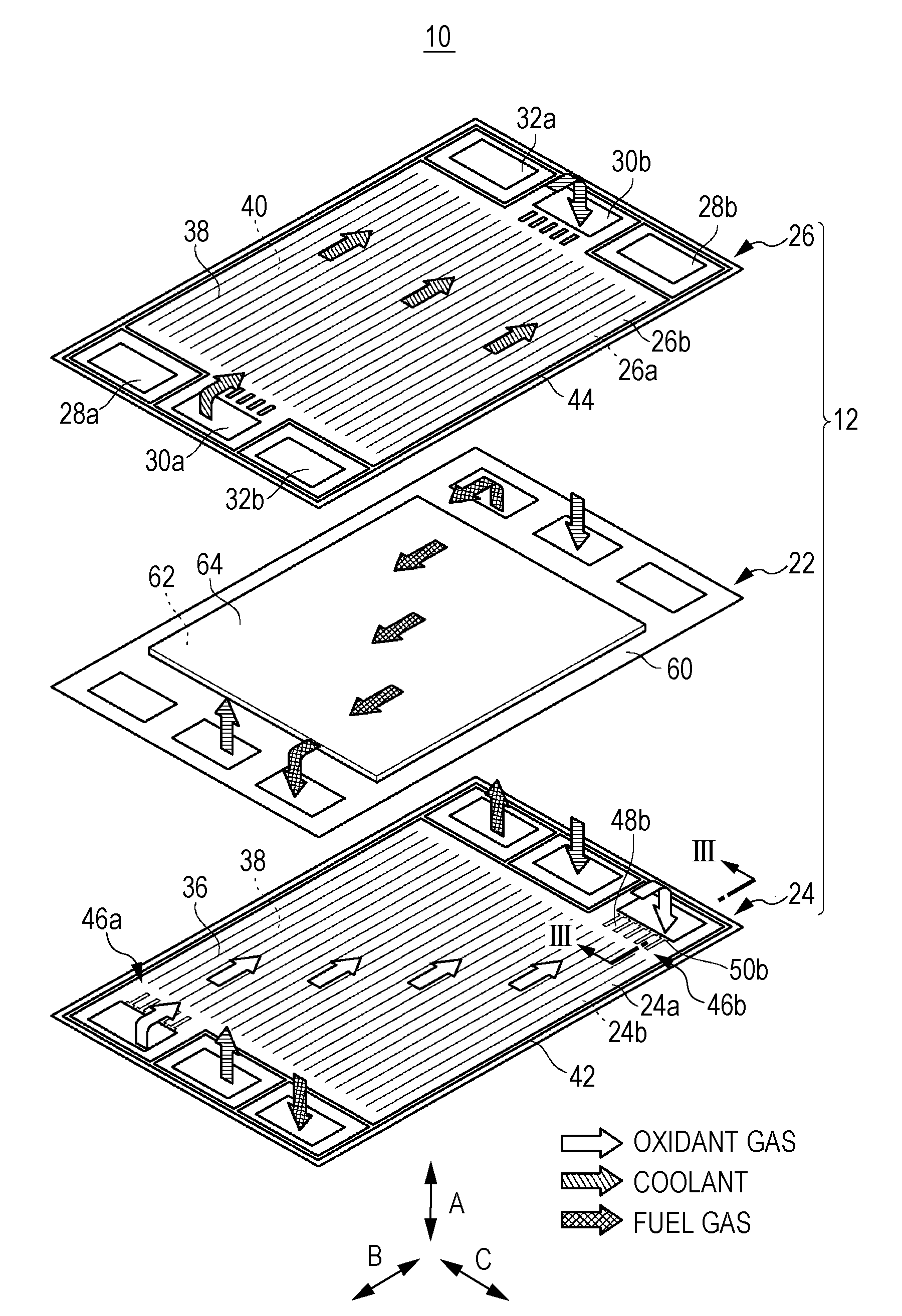
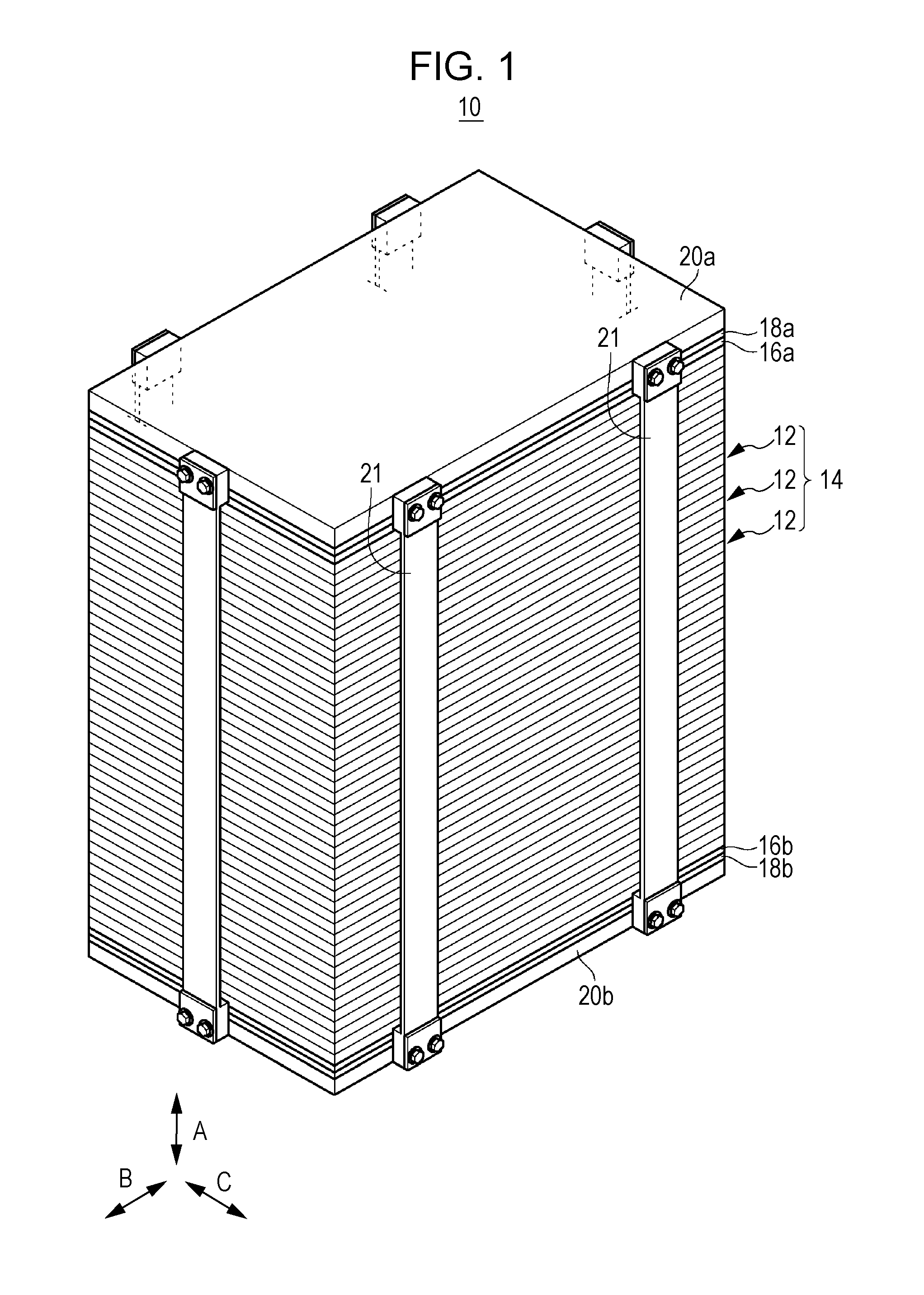
[0030]As illustrated in FIG. 1, a fuel cell stack 10 according to the present invention includes a stack 14 of a plurality of unit cells 12. The unit cells 12 are stacked in the direction of gravity (direction of arrow A) so that the electrode surfaces thereof extend horizontally. At one end (the upper end) of the stack 14 in the stacking direction (direction of arrow A), a terminal plate 16a, an insulator plate 18a, and an end plate 20a are disposed in this order toward the upper end. At the other end (the lower end) of the stack 14 in the stacking direction, a terminal plate 16b, an insulator plate 18b, and an end plate 20b are disposed in this order toward the lower end.

[0031]Ends of a plurality of connection bars 21 are fixed to the end plates 20a and 20b, so that a clamping force is applied to the end plates 20a and 20b in the stacking direction. Alternatively, a clamping force may be applied to the end plates 20a and 20b in the stacking direction by using a tie rod (not shown)...

second embodiment

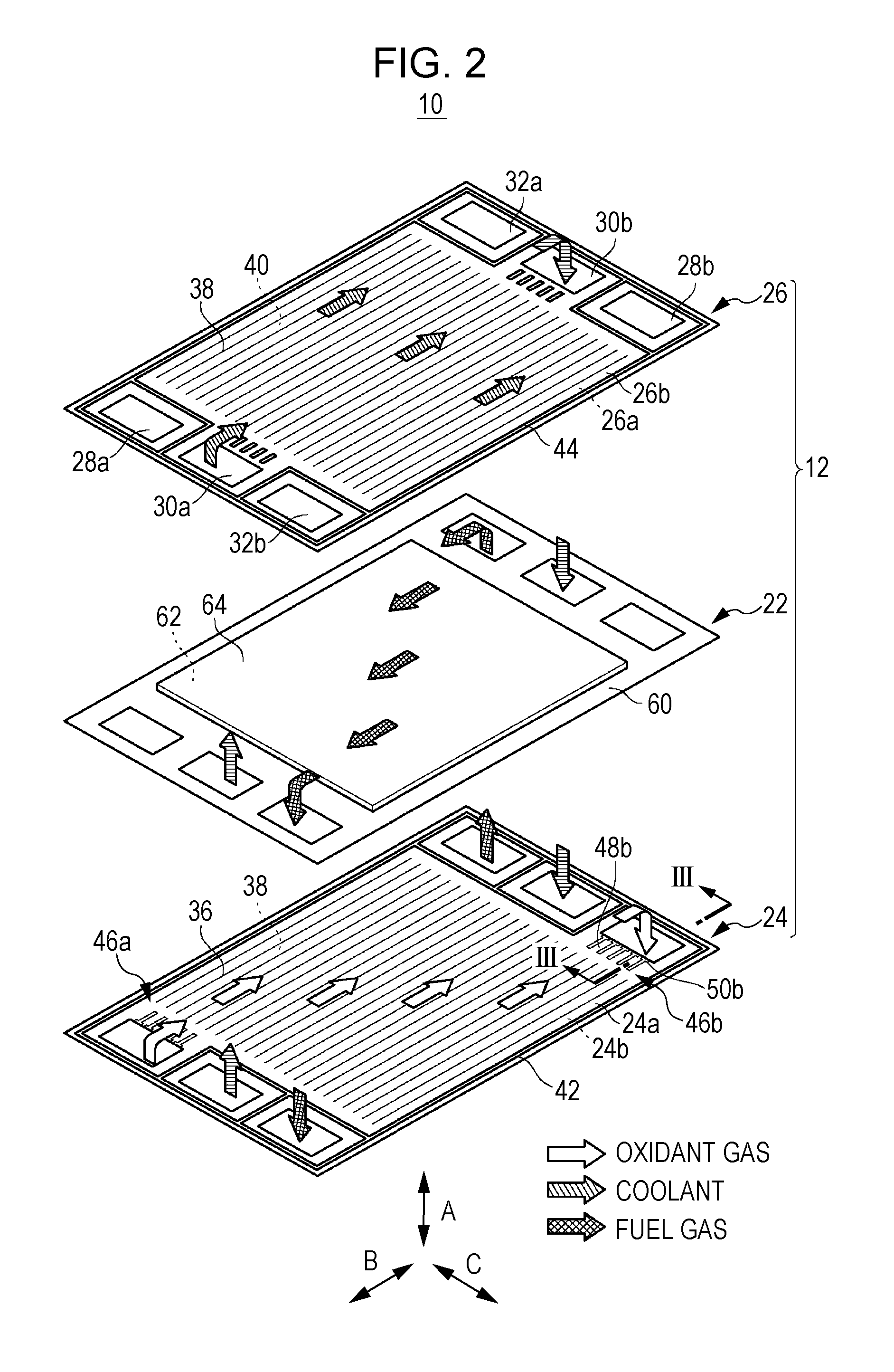
[0062]FIG. 9 is a perspective view of an outlet bridge portion 80 of a fuel cell stack according to the present invention.

[0063]Elements of the fuel cell stack that are the same as those of the fuel cell stack 10 according to the first embodiment will be denoted by the same numerals, and detailed description of such elements will be omitted. This also applies to third to seventh embodiments described below.

[0064]The outlet bridge portion 80, which is disposed between the oxidant gas outlet manifold 28b and the oxidant gas channel 36 of the first metal separator 24, will only be described below. The inlet bridge portion for the oxidant gas, the outlet bridge portion for the fuel gas, and the inlet bridge portion for the fuel gas have structures that are substantially the same as that of the outlet bridge portion 80, and the description of these bridge portions will be omitted.

[0065]The outlet bridge portion 80 forms the connection channels 48b. Projections 82, each projecting a dista...

third embodiment

[0067]FIG. 10 is a perspective view of an outlet bridge portion 90 of a fuel cell stack according to the present invention.

[0068]The outlet bridge portion 90 includes the protrusions 50b and projections 82 that are integrally formed. The protrusions 50b protrude toward the connection channels 48b. The projections 82 project into the oxidant gas outlet manifold 28b. Therefore, an effect the same as that of the first and second embodiments is produced with the third embodiment.


PUM


Abstract

A fuel cell stack includes a plurality of unit cells stacked in a stacking direction substantially along a direction of gravity. Each of the plurality of unit cells includes a first metal separator, a second metal separator, and a membrane electrode assembly sandwiched between the first metal separator and the second metal. A reactant gas channel allows a reactant gas to flow along a surface of each of the first and second metal separators. A reactant gas inlet manifold and a reactant gas outlet manifold allow the reactant gas to flow the reactant gas inlet manifold and the reactant gas outlet manifold in the stacking direction. A bridge portion forms a connection channel to connect at least the reactant gas outlet manifold to the reactant gas channel. The bridge portion includes a guide portion to break a continuity of condensed water.

Description

CROSS-REFERENCE TO RELATED APPLICATIONS[0001]The present application claims priority under 35 U.S.C. §119 to Japanese Patent Application No. 2010-015903, filed Jan. 27, 2010, entitled “Fuel Cell Stack”. The contents of this application are incorporated herein by reference in their entirety.BACKGROUND OF THE INVENTION[0002]1. Field of the Invention[0003]The present invention relates to a fuel cell stack.[0004]2. Description of the Related Art[0005]A solid polymer electrolyte fuel cell, for example, includes unit cells. Each of the unit cells includes a membrane electrode assembly (MEA) and separators sandwiching the MEA therebetween. The MEA includes an electrolyte membrane (electrolyte), which is a polymer ion-exchange membrane, and an anode electrode and a cathode electrode sandwiching the electrolyte membrane therebetween.[0006]When using this type of fuel cell for an automobile, a certain number (for example, tens or hundreds) of unit cells are stacked so as to form a fuel cell s...

Claims


Application Information

Patent Timeline
IPC IPC(8): H01M8/04H01M8/24
CPCH01M8/0206H01M8/0247H01M8/04201Y02T90/32H01M2250/20Y02E60/50H01M2008/1095Y02T90/40
Inventor TANAKA, HIROYUKISUGITA, NARUTOSHIISHIDA, KENTAROANDO, KEISUKE
Owner HONDA MOTOR CO LTD
Features
  • Generate Ideas
  • Intellectual Property
  • Life Sciences
  • Materials
  • Tech Scout
  • Unparalleled Data Quality
  • Higher Quality Content
  • 60% Fewer Hallucinations
Learn More