Connector

Active Publication Date: 2011-07-28
SUMITOMO WIRING SYST LTD
View PDF17 Cites 9 Cited by
  • Summary
  • Abstract
  • Description
  • Claims
  • Application Information

AI Technical Summary

Benefits of technology

[0010]The jig insertion opening is formed in a surface adjacent and orthogonal to the surface that has the retainer mount opening and accordingly the jig insertion opening does not extend over a plurality of terminal accommodating chambers. Thus, foreign substances are not likely to enter the jig insertion opening and become deposited over a plurality of terminal accommodating chambers. Further, the blocking wall of the retainer blocks the flow path from the jig insertion opening into the terminal accommodating chamber at a side of the jig insertion opening toward the terminal accommodating chamber. Thus, foreign substances will not enter the terminal accommodating chambers through the jig insertion opening. As a result, a large amount of foreign substances will not accumulate in the terminal accommodating chambers and consequently short circuits will not be caused by the deposition of foreign substances over the terminal fittings.
[0011]The retainer preferably has plural locking pieces for locking the retainer in the retainer mount opening. The blocking wall preferably is between two locking pieces juxtaposed in a direction parallel with an inserting direction of the terminal fittings. A projecting height of the blocking wall preferably is equal to projecting heights of the locking pieces. The blocking wall blocks the flow path from the jig insertion opening into the terminal accommodating chamber. However, a small clearance unavoidably is formed between the retainer mount opening and the retainer due to an assembling error and, hence, it is difficult for the blocking wall to close the jig insertion opening completely. A distance from the jig insertion opening to the terminal accommodating chamber may be extended as much as possible for maximally preventing foreign substances that enter a clearance between the retainer mount opening and the blocking wall from reaching the interior of the terminal accommodating chamber. Accordingly, the projecting height of the blocking wall preferably equals projecting heights of

Problems solved by technology

However, a small clearance unavoidably is formed between the retainer mount opening and the retainer due to an a

Method used


Image

  • Connector
  • Connector
  • Connector

Examples


Example

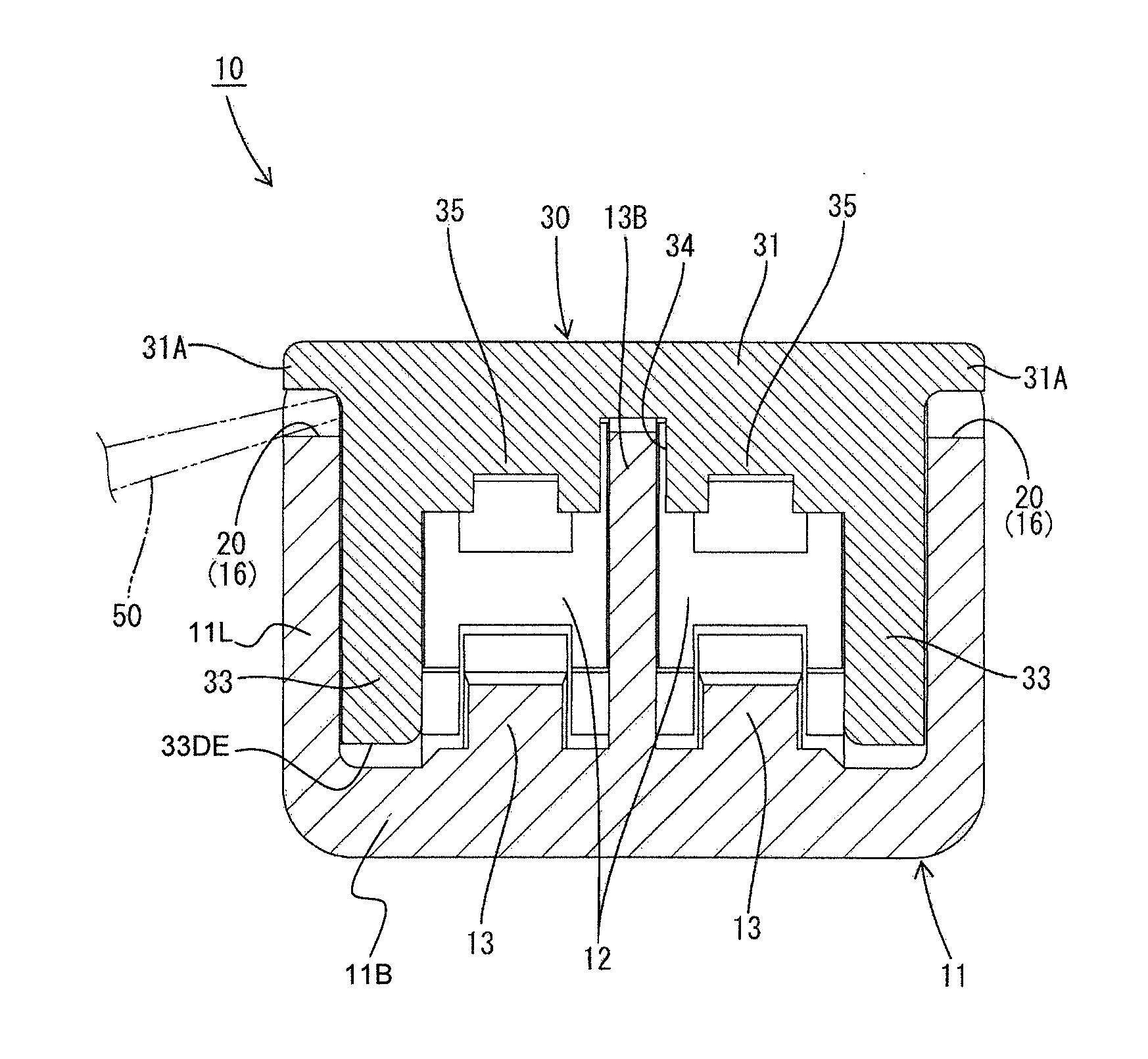
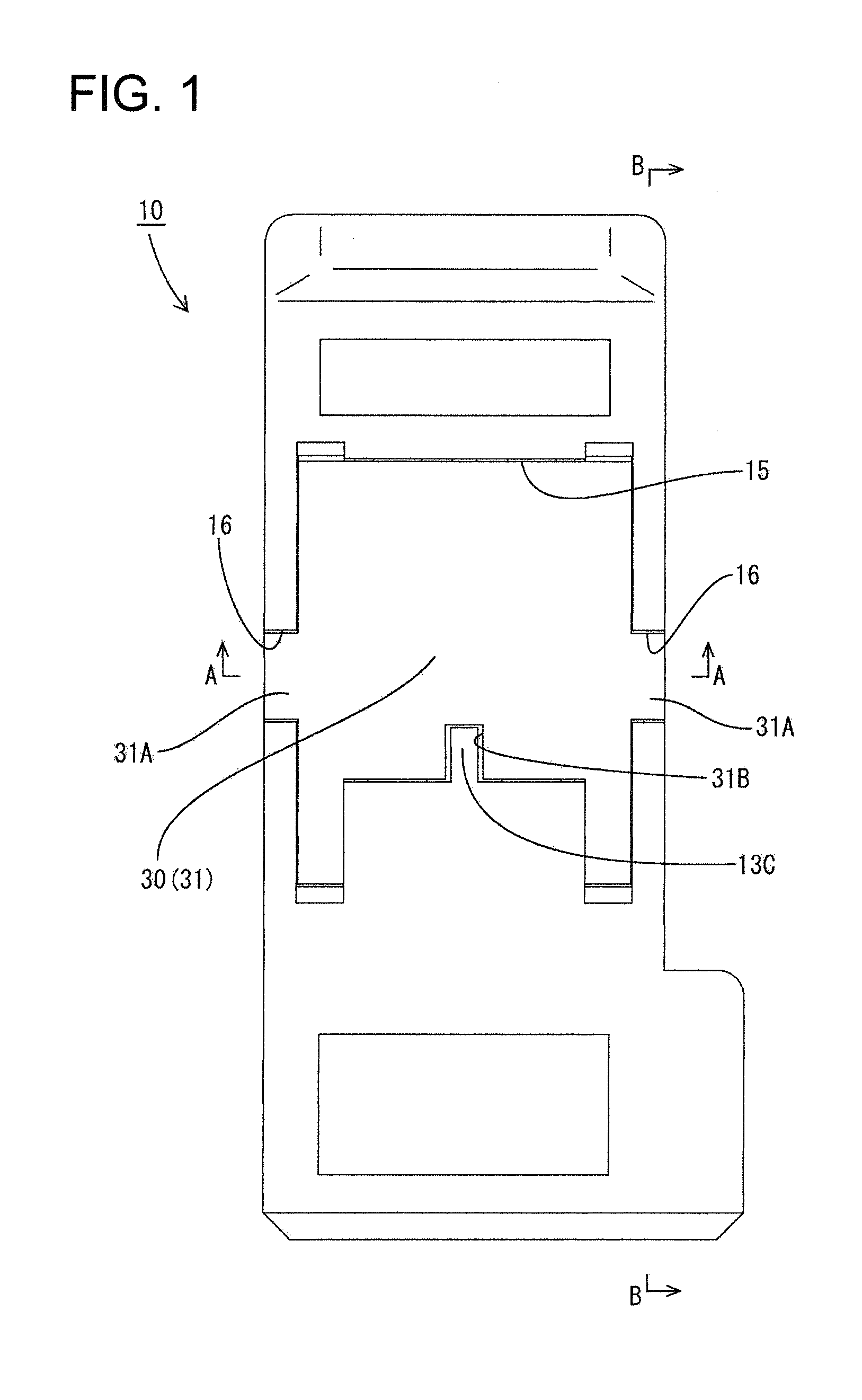
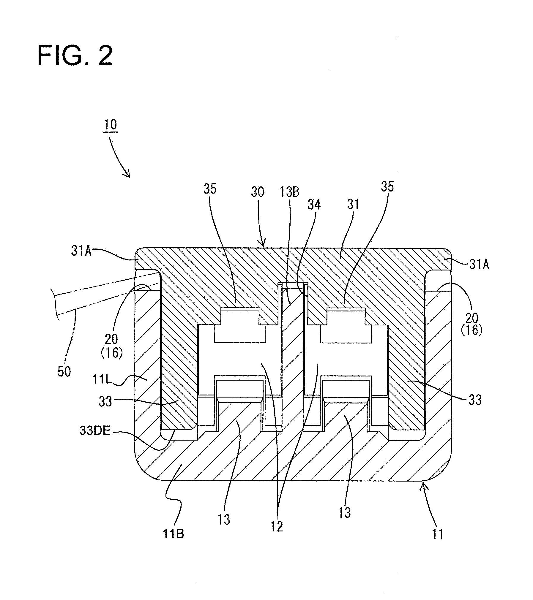
[0030]A connector in accordance with one embodiment of the invention is identified by the numeral 10 in FIGS. 1 to 7. The connector 10 has a substantially block-shaped housing 11 made e.g. of synthetic resin, a retainer 30 and female terminal fittings 25. In the following description, upper and lower ends of FIG. 1 are referred to as rear and front ends, a surface of the connector 10 where the retainer 30 is mounted is referred to as an upper surface and a lateral direction is referred to as a width direction.

[0031]Two cavities 12 penetrate the housing 11 in forward and backward directions and are arranged substantially side by side in the width direction, as shown in FIGS. 2, 6 and 8, to define terminal accommodating chambers. The housing 11 has a bottom wall 11B and a partition wall 13 extends vertically up from the bottom wall 11B to partition the two cavities 12. The partition wall 13 includes a front part 13A, an intermediate part 13B and a rear part (not shown). The front part...


PUM


Abstract

A connector has a housing (11) with terminal accommodating chambers (12) for receiving terminal fittings (25). A retainer mount opening (15) extends into one surface of the housing (10) and receives a retainer (30) for locking the terminal fittings (25) in the terminal accommodating chambers (12). Cutouts (16) extend from an opening edge of the retainer mount opening (15) into adjacent side surfaces of the housing (11) and form jig insertion openings (20) that can receive jigs (50) for detaching the retainer (30). The retainer (30) includes blocking walls (33) for blocking flow paths from the jig insertion openings (20) into terminal accommodating chambers (12), thereby preventing foreign substances from entering the terminal accommodating chambers (12) and causing a short circuit.

Description

BACKGROUND OF THE INVENTION[0001]1. Field of the Invention[0002]The invention relates to a connector provided with a retainer for retaining terminal fittings.[0003]2. Description of the Related Art[0004]Japanese Unexamined Patent Publication No. 2008-243692 discloses a connector with a housing that has terminal accommodating chambers that are separated laterally by partition walls. Terminal fittings are inserted from behind into the respective terminal accommodating chambers. A retainer mount opening is formed in an outer wall of the housing and communicates with the terminal accommodating chambers. A retainer is inserted into the retainer mount opening and has locking projections that engage steps on the terminal fittings to restrict movement of the terminal fittings in a withdrawing direction. A jig insertion opening is formed at an edge of the retainer and can receive a jig for detaching the retainer. The jig insertion opening is formed over a plurality of terminal accommodating ...

Claims


Application Information

Patent Timeline
IPC IPC(8): H01R13/514
CPCH01R13/52H01R13/4361
Inventor HIRANO, SHINJI
Owner SUMITOMO WIRING SYST LTD
Why Eureka
Try Eureka