Electrochemical machining device for multi-taper inner bores

A machining device and inner hole technology, applied in the field of multi-taper inner hole electrolytic machining device, can solve the problems of large cutting area, unstable machining process, loss of tools, etc., to improve production efficiency, reduce tool consumption, and improve reliability Effect

Inactive Publication Date: 2013-09-04
CHONGQING WANGJIANG IND
View PDF5 Cites 0 Cited by
  • Summary
  • Abstract
  • Description
  • Claims
  • Application Information

AI Technical Summary

Problems solved by technology

[0003] ① CNC boring and turning processing, the tool bar is longer during CNC turning, prone to vibration, poor surface roughness, low efficiency, high cost, surface quality and position accuracy can not meet the requirements
[0004] ② Forming reaming processing, the cutting area is large, the tool cost is high, the processing quality is restricted by the hardness of the material, it is difficult to process materials with high hardness, especially for parts after quenching
[0005] ③Electric pulse processing, due to the loss of tools in the processing process, the processing process is unstable and the processing process cannot be controlled
[0008] (1) The flow field distribution and margin matching ratio of the cathode are not easy to optimize, and the trial production cycle is long in the early stage of design;
[0009] (2) It is difficult to control the balance gap in the processing process, and it is difficult to achieve the best effect;
[0010] (3) The structure of the cathode is complex and difficult to process

Method used


Image

  • Electrochemical machining device for multi-taper inner bores
  • Electrochemical machining device for multi-taper inner bores
  • Electrochemical machining device for multi-taper inner bores

Examples


Embodiment Construction

[0025] Below in conjunction with accompanying drawing and process, the present invention will be further described.

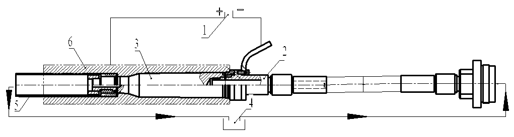
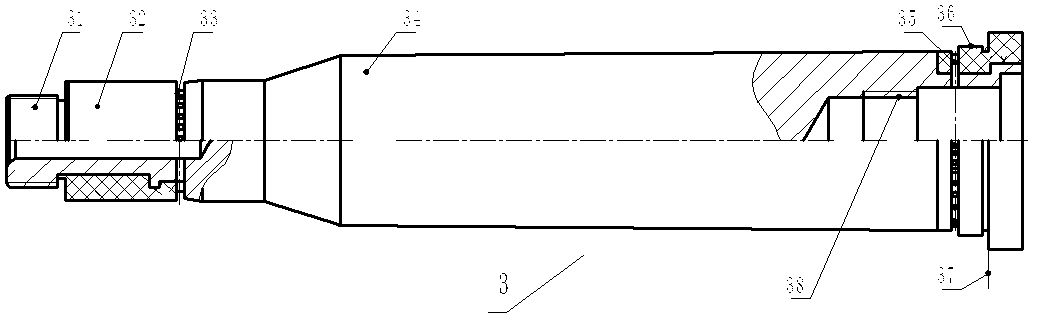
[0026] see figure 1 , figure 2 and image 3 A multi-taper inner hole electrolytic machining device shown includes a power source 1, a liquid-conducting and conductive component 2, a cathode component 3, an electrolyte system 4 and a positioning and draining component 5;

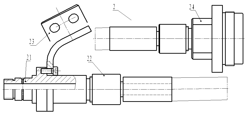
[0027] The liquid-guiding conductive assembly 2 includes a machine tool connector 24, a high-pressure liquid pipe connector 22 connected to the machine tool connector at one end, a cathode connector 21 connected to the other end of the high-pressure liquid pipe connector, and positioned on the cathode connector. The negative cable connecting row 23;

[0028] The right end of the positioning drain assembly 5 is connected to the left end of the cathode joint 21, and placed in the pre-hole of the processed member 6 together with the cathode member 3;

[0029] The electrolyte system 4 communi...


PUM


Abstract

The invention discloses an electrochemical machining device for multi-taper inner bores. The device comprises a power supply, a liquid and electricity conducting component, a cathode member, an electrolyte system and a positioning drainage component, and is characterized in that: the liquid and electricity conducting component comprises a machine tool connector, a high-pressure liquid tube connector of which one end is correspondingly connected with the machine tool connector, a cathode connector connected with the other end of the high-pressure liquid tube connector, and a negative cable connecting bar positioned on the cathode connector; a right end of the positioning drainage component is connected with a left end of the cathode connector; the positioning drainage component and the cathode member are arranged in a preformed hole of a machined member; the electrolyte system is communicated with the machine tool connector and the positioning drainage component through a pipeline respectively; and the power supply is connected with the negative cable connecting bar of the liquid and electricity conducting component and the machined member through a lead respectively. The requirements on machining accuracy of the surface dimension and position of a multi-taper inner bore are met, the production efficiency is improved by 5 times, the energy consumption is reduced to be 1 / 3 of that of machining, and the reliability is obviously improved.

Description

technical field [0001] The invention relates to an electrolytic machining device, in particular to a multi-taper inner hole electrolytic machining device. Background technique [0002] In the antiaircraft artillery used for artificial rainfall enhancement, the multi-taper inner hole charge chamber is an inevitable constituent element of the antiaircraft artillery ammunition launch. For example, some processing objects not only have many conical surfaces, high surface roughness, particularly deep inner hole, large aspect ratio, but also high requirements for the size and position accuracy of each conical surface, and the hardness and strength are further increased after heat treatment. , which brings great difficulty to processing and manufacturing. Using conventional processing methods, it is very difficult to process quenched components, which not only has low efficiency, large energy consumption, but also high cost. The current processing methods mainly include: [0003...

Claims


Application Information

Patent Timeline
Patent Type & Authority Patents(China)
IPC IPC(8): B23H9/14B23H3/04
Inventor 苏鹏张波李定军
Owner CHONGQING WANGJIANG IND
Why Eureka
Try Eureka