Apparatus for removing interference between neighbor cells in a radio communication system, and method for same

Active Publication Date: 2011-07-28
SEOUL NAT UNIV R&DB FOUND
View PDF5 Cites 15 Cited by
  • Summary
  • Abstract
  • Description
  • Claims
  • Application Information

AI Technical Summary

Benefits of technology

[0008]The present invention has been made keeping in mind the above problems occurring in the prior art, and an object of the present invention is to provide an apparatus and method for cancelling interference between neighboring cells in a wireless communication system, wh

Problems solved by technology

Generally, in a wireless communication system, in particular, in a multi-cell environment in which all cells use the same frequency band, terminals present on the boundary of each cell have a considerably limited system capacity near the cell boundary due to a large number of interference signals from neighboring cells.
The reason for the phenomenon whereby performance on the cell boundary is greatly deteriorated in this way is that a Signal-to-Interference-Noise power Ratio (SINR) decreases due to interference between neighboring cells.
Thus, such a technique is disadvantageous in that it is considerably inefficient in an environment in which a number of neighboring cell interference events equal to or greater than the number of receiving antennas are present.
Meanwhile, a conventional Maximum Likelihood (ML) technique can guarant

Method used


Image

  • Apparatus for removing interference between neighbor cells in a radio communication system, and method for same
  • Apparatus for removing interference between neighbor cells in a radio communication system, and method for same
  • Apparatus for removing interference between neighbor cells in a radio communication system, and method for same

Examples


Example

DESCRIPTION OF REFERENCE NUMERALS OF PRINCIPAL ELEMENTS IN THE DRAWINGS

[0029]910: receiving unit[0030]920: first determination unit[0031]930: second determination unit[0032]940: third determination unit[0033]950: estimation unit

BEST MODE

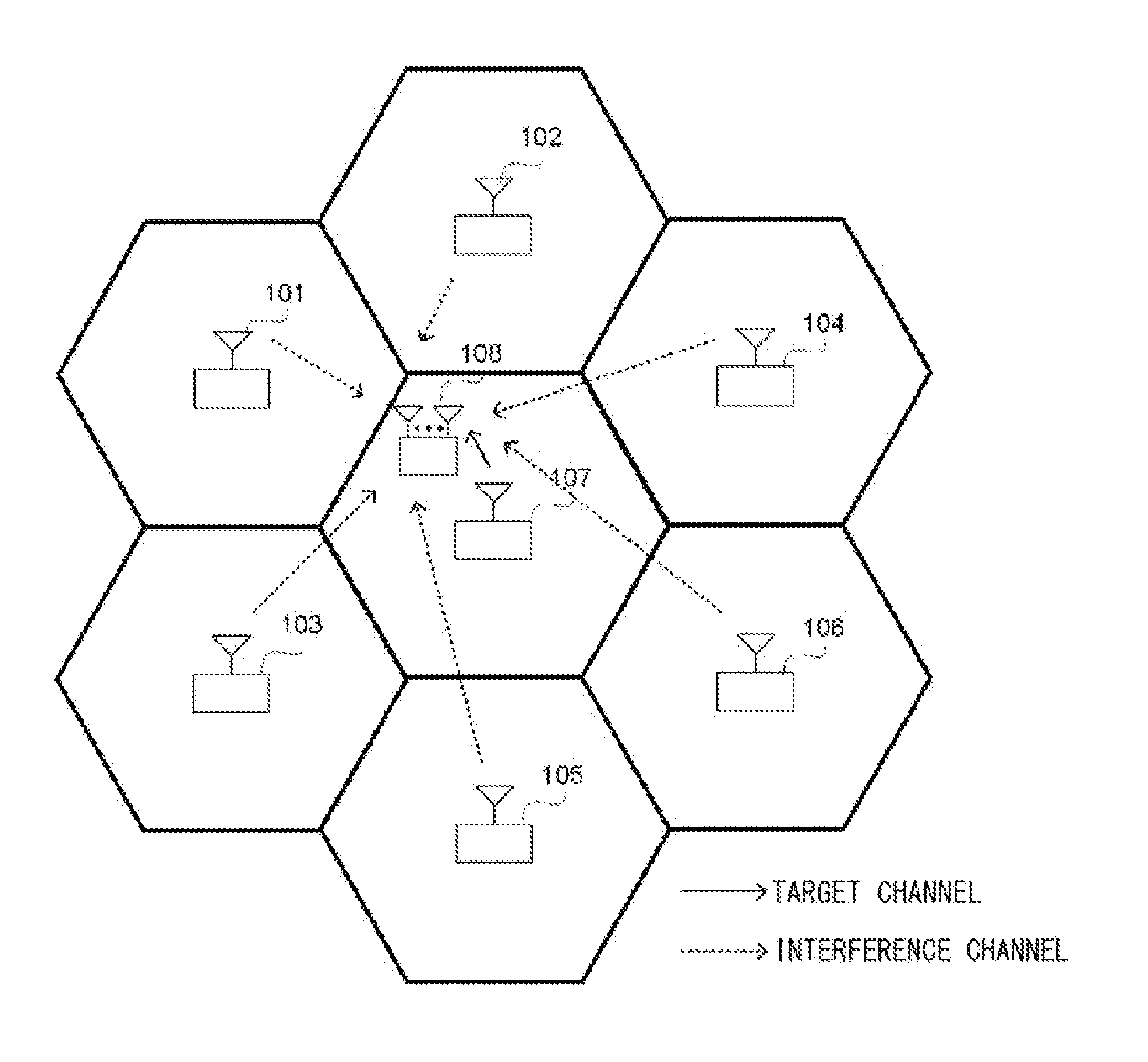
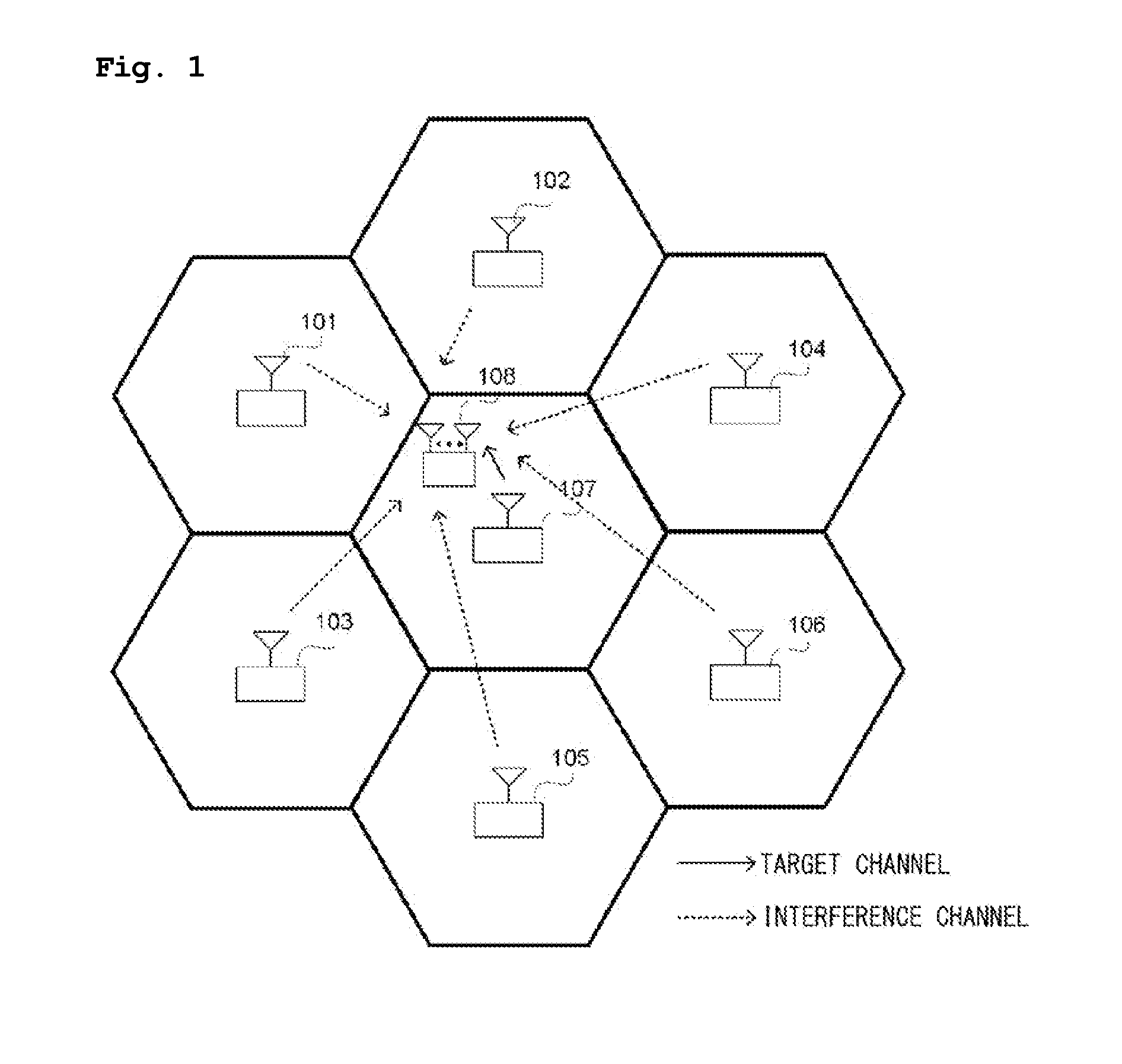
[0034]Hereinafter, an apparatus and method for cancelling interference between neighboring cells in a wireless communication system according to embodiments of the present invention will be described in detail with reference to FIGS. 1 to 9.

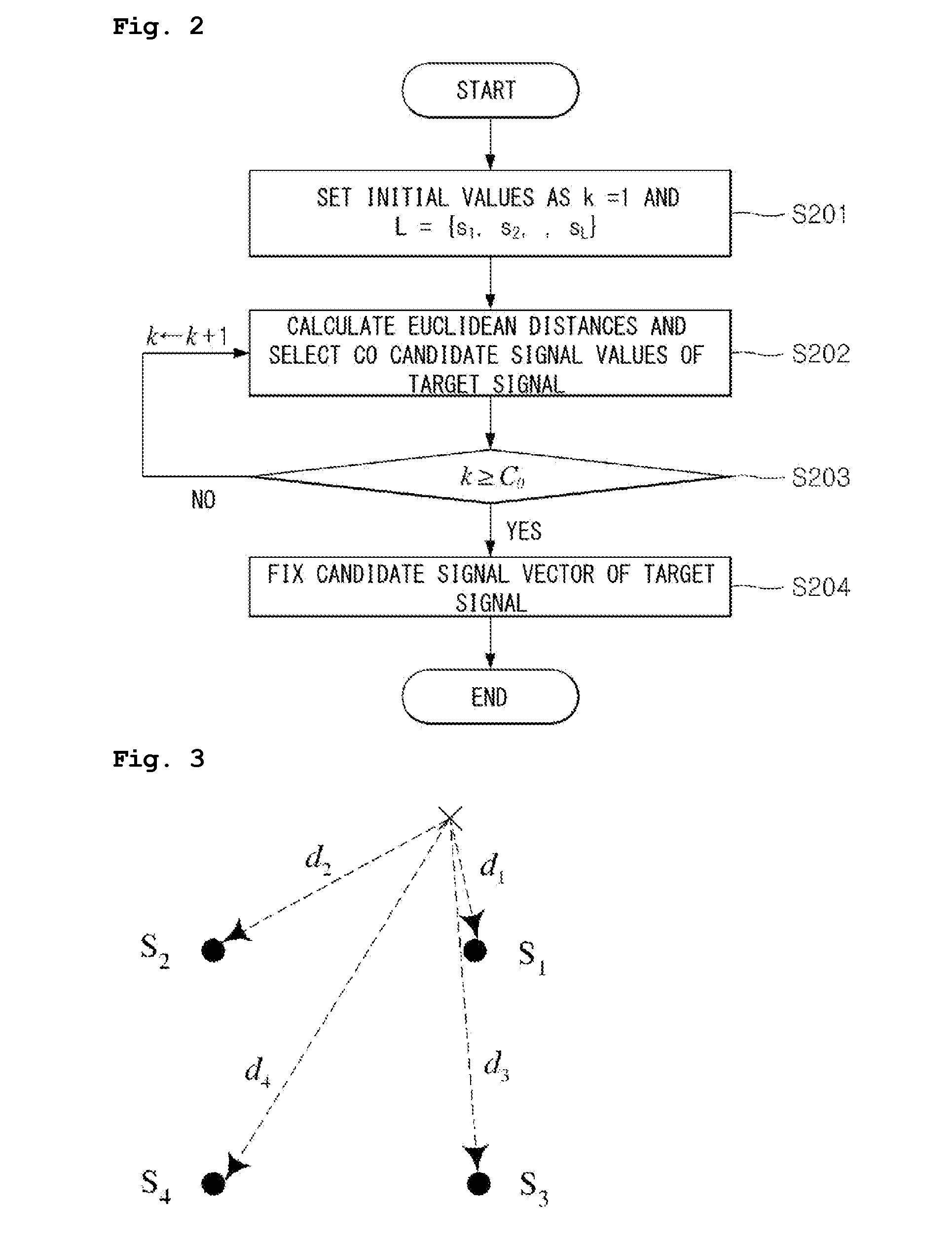
[0035]The present invention proposes a scheme for cancelling interference between neighboring cells. That is, the present invention can estimate a target signal or an interference signal by applying only target and interference signal vectors, which have been selected using a Minimum Mean Square Error-Ordered Successive Interference Cancellation (MMSE-OSIC) technique, to a Maximum Likelihood (ML) technique. In this case, the number of target and interference signal vectors can be determined in consideration of the...


PUM


Abstract

The present invention relates to an apparatus for removing interference between neighbor cells in a radio communication system, and to a method for same. The apparatus according to the present invention includes a receiving unit which receives receiving power information and signal-to-noise ratio information of a neighbor cell base station from multiple receiving antennas, a first determination unit for determining the number of major neighbor cell interference signals by using the received receiving power information and the signal-to-noise ratio information, a second determination unit for determining a candidate signal vector of a target signal in accordance with the determined number of major neighbor cell interference signals, the received signal-to-noise ratio, and the number of the multiple receiving antennas, a third determination unit for determining a candidate signal matrix of the major neighbor cell interference signals on the basis of the determined candidate signal vector of the target signal, and an estimation unit for estimating signals transmitted from the target base station or the neighbor base station by applying the determined candidate signal matrix of the major neighbor cell interference signals to the method of maximum likelihood. Whereby, the present invention removes interference between neighbor cells in an efficient manner, maintains the performance thereof, and reduces complexity at the receiving end.

Description

TECHNICAL FIELD[0001]The present invention relates to an apparatus and method for cancelling interference between neighboring cells in a wireless communication system.BACKGROUND ART[0002]Generally, in a wireless communication system, in particular, in a multi-cell environment in which all cells use the same frequency band, terminals present on the boundary of each cell have a considerably limited system capacity near the cell boundary due to a large number of interference signals from neighboring cells. The reason for the phenomenon whereby performance on the cell boundary is greatly deteriorated in this way is that a Signal-to-Interference-Noise power Ratio (SINR) decreases due to interference between neighboring cells.[0003]In order to solve this problem, research into methods of minimizing the influence of interference signals between neighboring cells has been widely carried out.[0004]In particular, a conventional Minimum Mean Square Error (MMSE) technique is known as a consider...

Claims


Application Information

Patent Timeline
IPC IPC(8): H04B15/00H04B7/26
CPCH04B17/345H04B17/005
Inventor LEE, YONG HWANLEE, SEUNG-HWAN
Owner SEOUL NAT UNIV R&DB FOUND
Why Eureka
Try Eureka