
Electronic equipment and control method and control device thereof

A technology of electronic equipment and control method, which is applied in branch office equipment, telephone communication, electrical components, etc., and can solve problems such as low strength, low shell strength, and large shock feeling

Active Publication Date: 2021-01-22
VIVO MOBILE COMM CO LTD
View PDF10 Cites 2 Cited by
  • Summary
  • Abstract
  • Description
  • Claims
  • Application Information

AI Technical Summary

Problems solved by technology

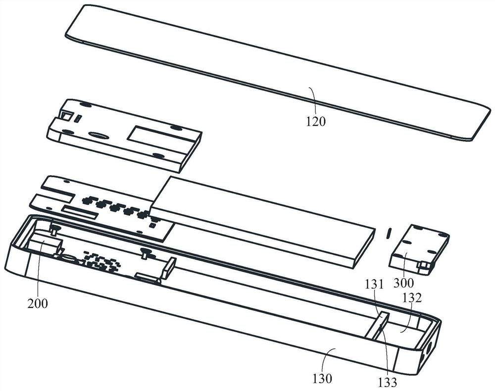
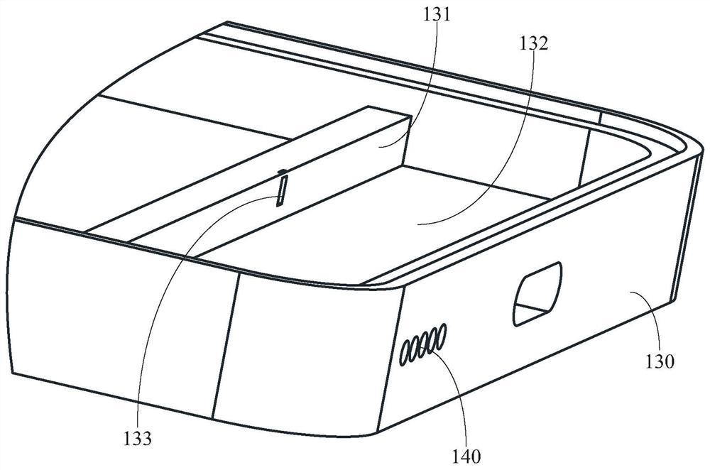
[0003] At present, most electronic equipments have housings, which can protect the internal components of electronic equipment. In order to save the manufacturing cost of electronic equipment, electronic equipment manufacturers will be urged to use low-cost housings. Such housings usually Thinner, or the strength of the material is lower, resulting in lower strength of the shell, because the back cavity of the receiver or speaker in the electronic device is formed by the shell, when the receiver or speaker vibrates, the receiver or speaker passes through the back cavity. It is easy to drive the shell with low strength to vibrate, which will cause electronic equipment to generate noise or large shock due to the vibration of the shell

Method used


Image

  • Electronic equipment and control method and control device thereof
  • Electronic equipment and control method and control device thereof
  • Electronic equipment and control method and control device thereof

Examples


Embodiment Construction

[0070] In order to make the purpose, technical solution and advantages of the present application clearer, the technical solution of the present application will be clearly and completely described below in conjunction with specific embodiments of the present application and corresponding drawings. Apparently, the described embodiments are only some of the embodiments of this application, not all of them. Based on the embodiments in this application, all other embodiments obtained by persons of ordinary skill in the art without making creative efforts belong to the scope of protection of this application.

[0071] The terms "first", "second" and the like in the specification and claims of the present application are used to distinguish similar objects, and are not used to describe a specific sequence or sequence. It is to be understood that the data so used are interchangeable under appropriate circumstances such that the embodiments of the application can be practiced in sequ...


PUM


Abstract

The invention discloses electronic equipment and a control method and device thereof, and the electronic equipment is characterized in that a first sound production module is disposed in a first accommodation cavity; and a second sounding module is arranged in the accommodating space. When the first sound production module is in the first working state, the second sound production module is in thesecond working state, the first sound production module outputs a first vibration signal to the shell, and the second sound production module outputs a second vibration signal to the shell; or, soundwaves emitted by the first sound production module form first sound waves in the first accommodating cavity, and sound waves emitted by the second sound production module form second sound waves in the first accommodating cavity; or, the first sound production module outputs a first vibration signal to the shell, and the sound wave emitted by the second sound production module forms a second sound wave in the first accommodating cavity; and the phase of the first vibration signal is opposite to the phase of the second vibration signal, the phase of the first sound wave is opposite to the phase of the second sound wave, and the problem of shell vibration during audio output of existing electronic equipment can be solved.

Description

technical field [0001] The present application relates to the technical field of communication equipment, and in particular to an electronic equipment, a control method and a control device thereof. Background technique [0002] With the rapid development of electronic equipment, the application of electronic equipment is becoming more and more extensive. Electronic equipment such as mobile phones and tablet computers play more and more roles in people's work, life, and entertainment. [0003] At present, most electronic equipments have housings, which can protect the internal components of electronic equipment. In order to save the manufacturing cost of electronic equipment, electronic equipment manufacturers will be urged to use low-cost housings. Such housings usually Thinner, or the strength of the material is lower, resulting in lower strength of the shell, because the back cavity of the receiver or speaker in the electronic device is formed by the shell, when the recei...

Claims


Application Information

Patent Timeline
IPC IPC(8): H04M1/19H04M1/72448
CPCH04M1/19H04M1/035H04R1/2873H04R2499/11H04R2499/15H04R1/02H04R1/028H04R1/2823H04R3/12
Inventor 陈俊辉李乐乐
Owner VIVO MOBILE COMM CO LTD
Learn More