Sample temperature regulator

a temperature regulator and sample technology, applied in the field of sample temperature regulators, can solve the problems of reducing the heating rate of aluminum blocks, affecting the performance of the device, so as to achieve the effect of simple structure, durable and inexpensive, and resistance to impacts and vibrations

Inactive Publication Date: 2006-01-24
EYELA CHINO
View PDF22 Cites 13 Cited by
  • Summary
  • Abstract
  • Description
  • Claims
  • Application Information

AI Technical Summary

Benefits of technology

[0011]The sample temperature regulators according to these aspects each have a simple structure and are resistant to impacts and vibrations, durable and inexpensive, since the heating block and the cooling block are combined with each other. Even if the heating block and the cooling block are combined with each other, the connecting plate made of a material having a thermal conductivity lower than that of the heating block and that of the cooling block or the cooling block made of a material having a thermal conductivity lower than that of the heating block limits the rate of heat transfer from the heating block to the cooling block, so that the temperature of the heating block can be regulated at a predetermined preset level while the temperature of the cooling block is maintained for a long time.
[0012]In this temperature regulator, a material having a thermal conductivity lower than that of the heating block is interposed between the heating block and a cooling mechanism, so that the refrigerant for cooling the cooling block is kept unsusceptible to the heat from the heating block. Thus, this temperature regulator can readily start cooling down of the heating block without waiting cooling of the heated refrigerant as has been necessary in the conventional temperature regulators. If the heating block is cooled to a preset temperature, the temperature of the heating block is maintained under temperature control of the heater. Further, when the heating block is heated, it can be heated at a high heating rate, because the refrigerant does not deprive of the heat of the heater.
[0013]Therefore, this temperature regulator carries out heating and cooling at high rates respectively compared with the conventional temperature regulators and can carry out accurate temperature regulation over a wide temperature range. Further, there is no need of replacing the refrigerant depending on the temperature range, the temperature regulator takes no trouble with cooling and heating. In addition, the higher the performance of the cooling equipment to be used, the higher becomes the cooling capacity. Use of cooling equipment having higher performance can give a cooling capacity in proportion to it.
[0015]If the cooling block is provided with a refluxing block to be brought into contact with upper parts of sample containers, the upper parts of the sample containers can be cooled with refluxing equipment having a simple structure. Further, the refluxing equipment having such a structure is resistant to vibrations. In addition, the temperature of the refluxing block can be reduced to around that of the cooling block, and if the cooling block is cooled to a cryogenic temperature, the refluxing temperature can be maintained at a low level. Thus, the temperature regulator can show increased refluxing performance in spite of its compact structure.

Problems solved by technology

However, the temperature regulator resorting to a peltier device failed to provide effective means, since the device involves problems that it has insufficient power relative to the quantity of sample contained in each sample container and cannot provide a sufficient temperature range, and that the device is expensive and has poor durability.
In addition, in the case of the low and high temperature external circulating system, the temperature of several liters of circulating fluid must be changed when the preset temperature range is to be changed, and the speed of increasing and decreasing the temperature is extremely low.
In the temperature regulator having an aluminum block provided with a refrigerant channel and a heater attached to the aluminum block, the refrigerant in the refrigerant channel deprives of the heat of the heater, when the aluminum block is heated after cooling, to lower the heating rate of the aluminum block and to increase the temperature of the refrigerant, lowering cooling efficiency of the refrigerant circulating system.
In addition, in this temperature regulator, if the heating temperature is higher than the boiling point of the refrigerant, the heating causes boiling of the refrigerant.
Further, in the temperature regulator having an aluminum block provided with a refrigerant channel and a heater attached to the aluminum block, the heater gives a large quantity of heat to the refrigerant.
Therefore, in the case where a plurality of aluminum blocks are arranged and are set to have different temperatures respectively, if there is a very great difference between the preset temperatures of the adjacent aluminum blocks, these aluminum blocks influence each other through the refrigerant, impeding accurate temperature regulation.
Therefore, it is difficult to maintain the aluminum blocks at different temperatures respectively for a long time unless the preset temperature ranges in the aluminum blocks do not differ greatly.
Further, it is not desired in an organic synthesis experiment that vaporized components formed by the heat of reaction mixtures in a sample container be released into the atmosphere.
In the case where a plurality of sample containers are subjected to refluxing treatment, a cooling mechanism including a water cooling pipe is attached to the reflux column mounted on each sample container, so that the greater the number of the sample containers is, the more troublesome become installation and removal of the reflux columns and cooling mechanisms.
Besides, if the sample containers each having a reflux column and a cooling mechanism are subjected as such to shaking, a strong shaking treatment can break the reflux columns and the cooling mechanisms.

Method used


Image

  • Sample temperature regulator
  • Sample temperature regulator
  • Sample temperature regulator

Examples


first embodiment

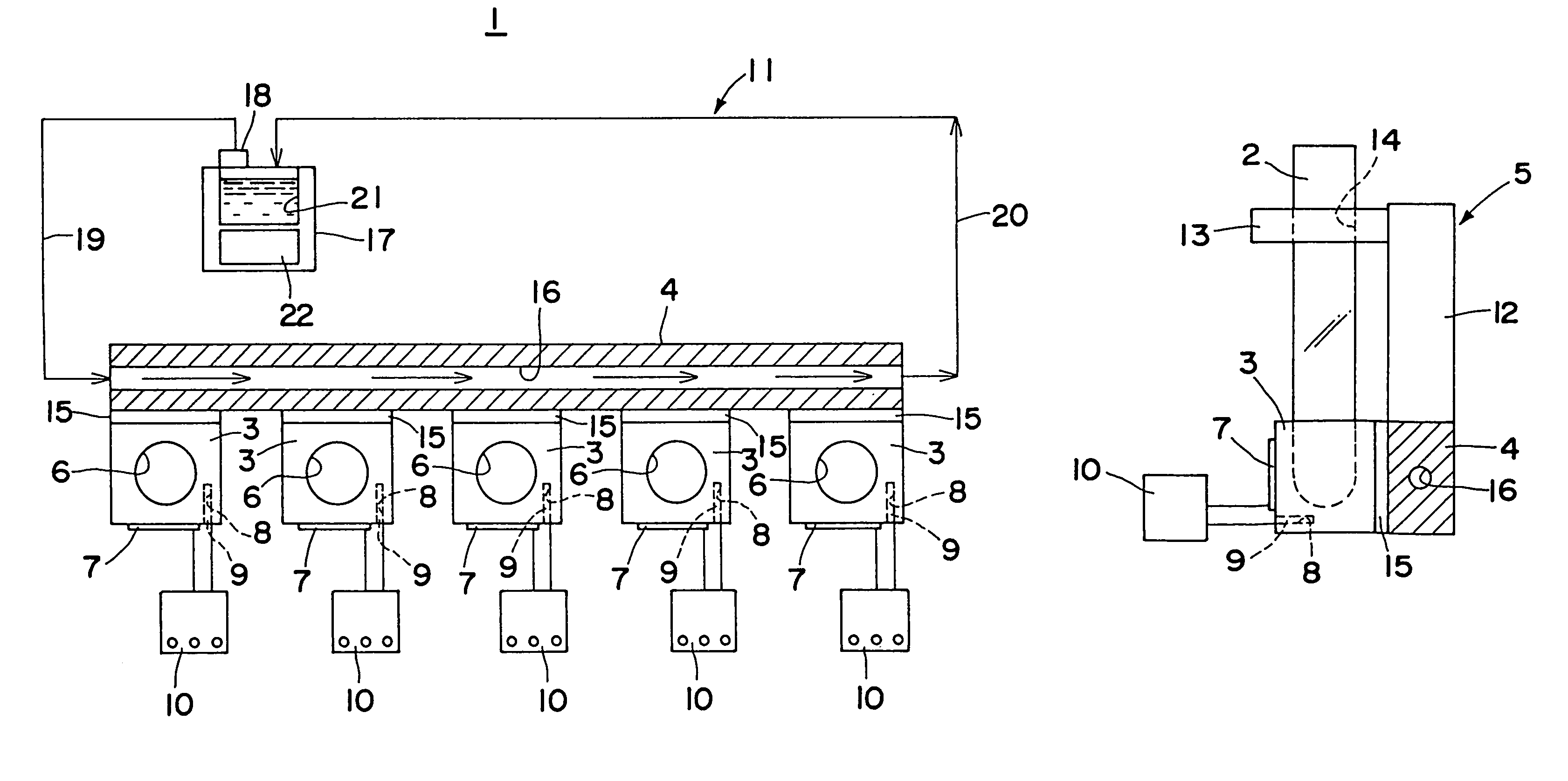
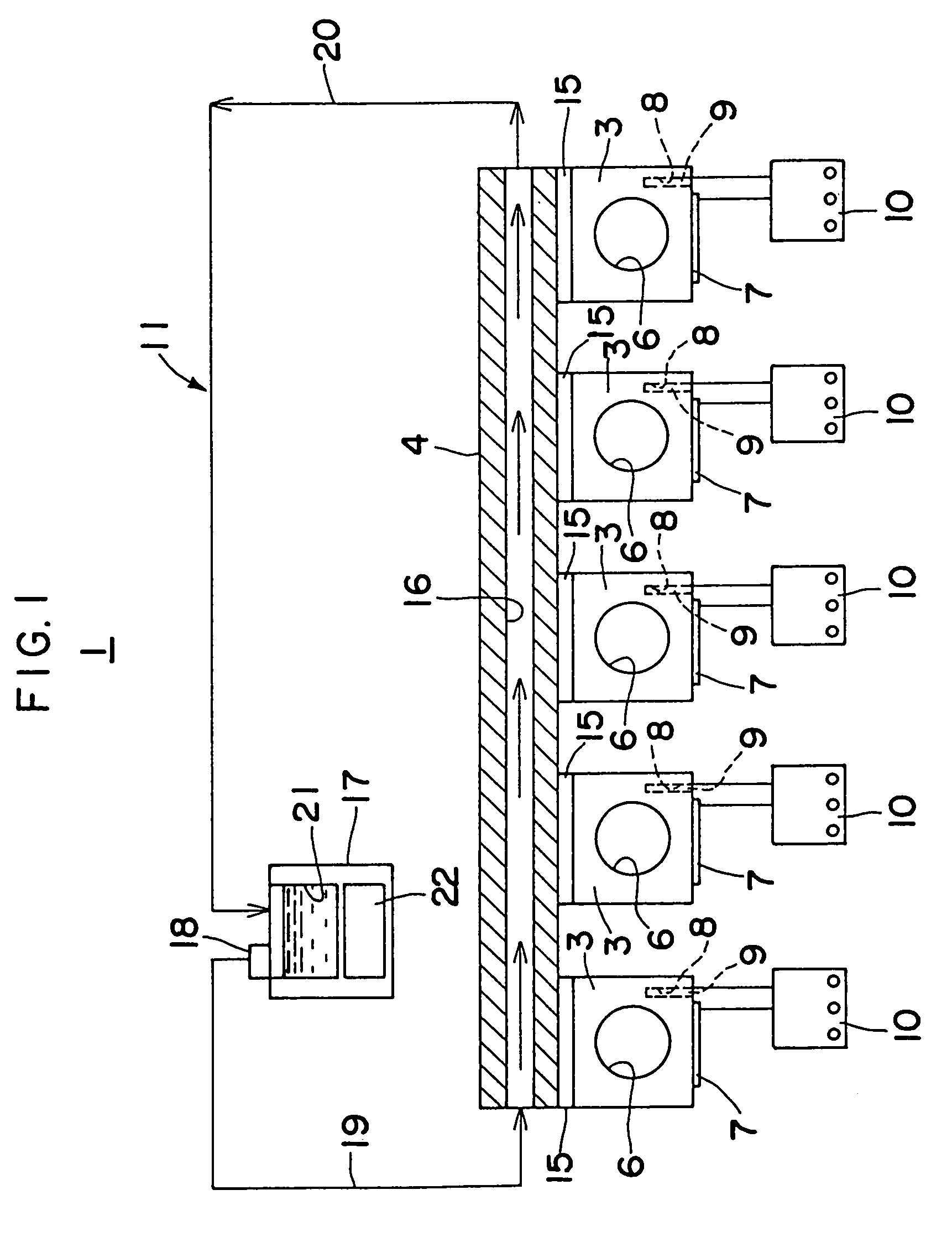
[0036]The cooling mechanism 11 in the temperature regulator 1 shown in FIGS. 1 to 3 has a circulating passage containing a refrigerant channel 16 defined longitudinally through the cooling block 4; an antifreeze cooling unit 17; a pipe 19 connecting the antifreeze cooling unit 17 to an inlet of the refrigerant channel 16 through a circulating pump 18; and a pipe 20 connecting an outlet of the refrigerant channel 16 to the antifreeze cooling unit 17. The cooling block 4 is cooled during the process that the antifreezing fluid supplied as a low-temperature refrigerant from the antifreeze cooling unit 17 flows from the inlet to the outlet of the refrigerant channel 16. Here, as the antifreeze cooling unit 17, for example, one having an antifreeze tank 21 and a cooler 22 disposed under the tank 21, as shown in FIG. 1, can be used.

second embodiment

[0037]The cooling mechanism 11 of the temperature regulator 1 shown in FIG. 4 has a circulating passage containing a metal pipe 32 with a closed end fitted in a through hole 31 defined longitudinally through the cooling block 4; a refrigerant injecting pipe 33 inserted to the metal pipe 32 through its opening to the closed end of the pipe 32; a vapor refrigerant cooling unit 34; a pipe 35 connecting the vapor refrigerant cooling unit 34 to the refrigerant injecting pipe 33; and a pipe 36 connecting the opening of the metal pipe 32 to the vapor refrigerant cooling unit 34. In the cooling block 4, the vapor refrigerant supplied from the vapor refrigerant cooling unit 34 and injected from the tip of the refrigerant injecting pipe 33 is cooled while it flows through the metal pipe 32 along the bottom to the opening thereof. As the vapor refrigerant cooling unit 34, there may be employed, for example, an immersion cooler provided with a cooling unit 37, as shown in FIG. 4.

third embodiment

[0038]The cooling mechanism 11 of the temperature regulator 1 shown in FIG. 5, contains a refrigerant channel 41 defined longitudinally through the cooling block 4; a low-temperature vapor refrigerant generator 42; a pipe 44 connecting a heating section 43 of the low-temperature vapor refrigerant generator 42 to an inlet of the refrigerant channel 41; and an exhaust pipe 45 connected to an outlet of the refrigerant channel 41. In the cooling block 4, the liquefied gas vaporized under heating in the heating section 43 is cooled while it flows from the inlet to the outlet of the refrigerant channel 41. Here, the liquefied gas serving as the low-temperature refrigerant is stored, for example, in a tank 46 in the low-temperature vapor refrigerant generator 42, as shown in FIG. 5.


PUM


Abstract

The sample temperature regulator is provided with a heating block (3) having a sample container holder (6) and a temperature-controllable heater (7) and with a cooling block (4) having a cooling mechanism (11). These two blocks are combined with each other through a connecting plate (15) made of a material having a thermal conductivity lower than those of these blocks. This constitution can reduce heat transfer between the heating block and the cooling block and allows them to have wide temperature regulating ranges, as well as increased heating capacity and cooling capacity, respectively. Further, this constitution makes the structure of the temperature regulator simple and compact, so that the regulator has increased durability and can be offered at a low price.

Description

TECHNICAL FIELD[0001]The present invention relates to a sample temperature regulator for regulating temperatures of samples in containers such as test tubes, micro-tubes, micro-plates and flasks at preset levels respectively. This temperature regulator is utilized in reacting sections of thermostats and organic synthesizers.BACKGROUND ART[0002]Such temperature regulator frequently used includes one composed essentially of an aluminum block, and there is known one in which the aluminum block is heated with a heater or one in which the aluminum block is cooled with a refrigerant flowing through a refrigerant channel. There is another type of temperature regulator which carries out both heating and cooling in one aluminum block for applications in tests which require cooling after heating or vice versa. The temperature regulator carrying out both heating and cooling in one aluminum block includes, for example, one resorting to a device or to a low and high temperature external circulat...

Claims


Application Information

Patent Timeline
Patent Type & Authority Patents(United States)
IPC IPC(8): F25B29/00G05D23/19
CPCG05D23/1934
Inventor OHKI, YUTA
Owner EYELA CHINO
Why Eureka
Try Eureka