Connector

a technology of connecting rods and connectors, applied in the direction of coupling device details, coupling device connection, electric discharge lamps, etc., can solve the problems of difficult to maintain the durability of electrical connectors, the placement of electrical connectors thereof, and further difficulty in maintaining durability, so as to achieve the effect of simple and easy connection

Active Publication Date: 2010-09-14
JST MFG CO LTD +1
View PDF37 Cites 15 Cited by
  • Summary
  • Abstract
  • Description
  • Claims
  • Application Information

AI Technical Summary

Benefits of technology

[0007]It is an object of the present invention to provide a connector capable of being simply and easily connected without loss of electrical continuity even in a harsh environment.
[0008]It is another object of the present invention to provide a connector which has resistance to high-acceleration vibration, and is lightweight and capable of being downsized.

Problems solved by technology

However, in the vicinity of a power source, in particular, a direct fuel-injection engine or the like, electrical connectors thereof are placed in a harsh environment.
That is, because high-acceleration vibration is caused in the vicinity of such a power source, housings of an electrical connector are easily worn away or made defective, which makes it difficult to maintain the durability of the electrical connectors.
Further, when high-acceleration vibration of a power source corresponds to a natural frequency of an electrical connector itself, the electrical connector itself falls into a mechanical resonance condition, which makes it further difficult to maintain the durability thereof.
However, installation of an electrical connector by use of a leader cable results in an increase in the number of components.
Therefore, the greater the number of connectors to be installed becomes, the greater the increase in man-hours for connection.

Method used


Image

  • Connector
  • Connector
  • Connector

Examples


Embodiment Construction

[0039]Hereinafter, an embodiment according to the present invention will be described. In the embodiment, an electrical connector will be explained with an example of a connector.

One Embodiment

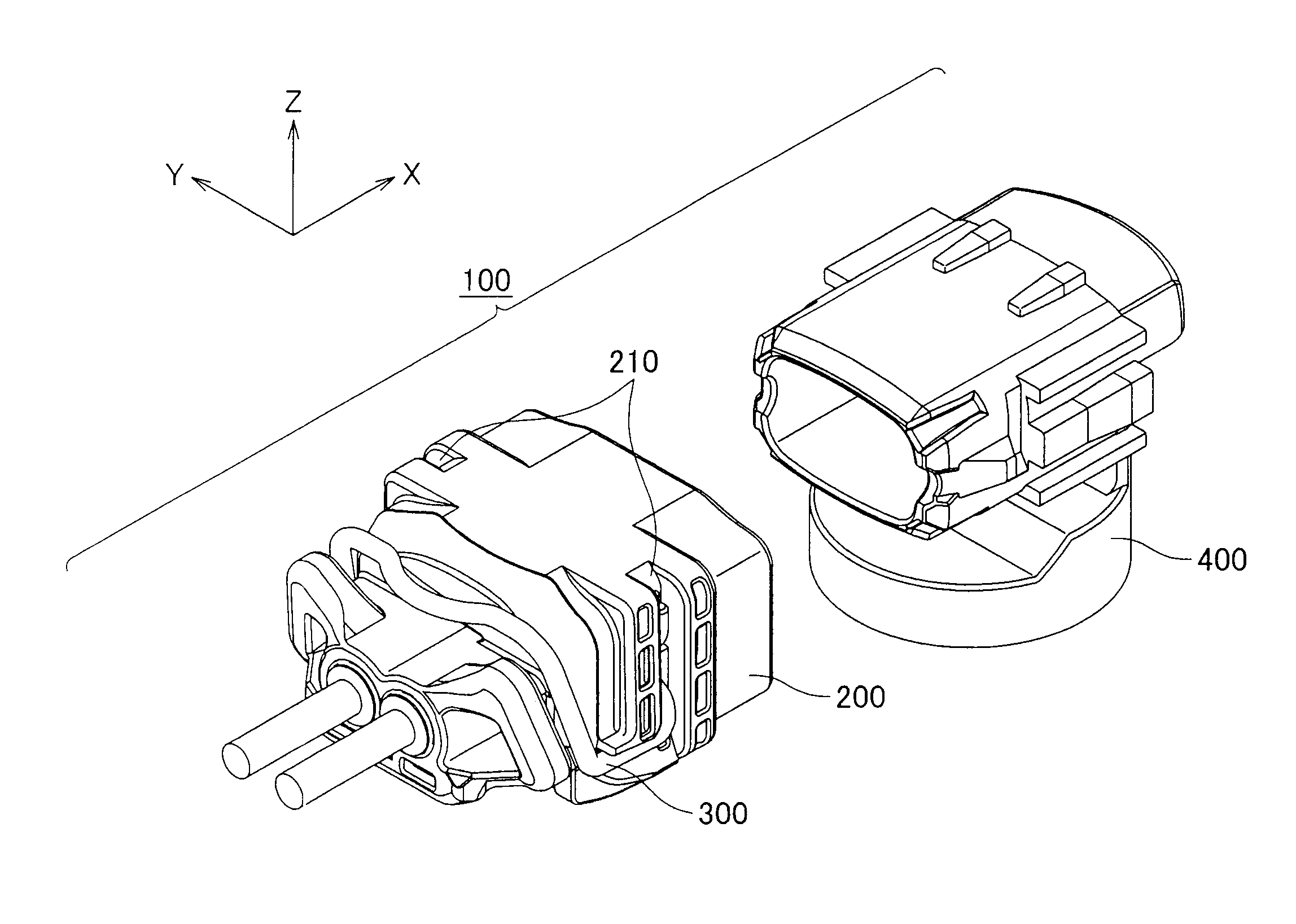
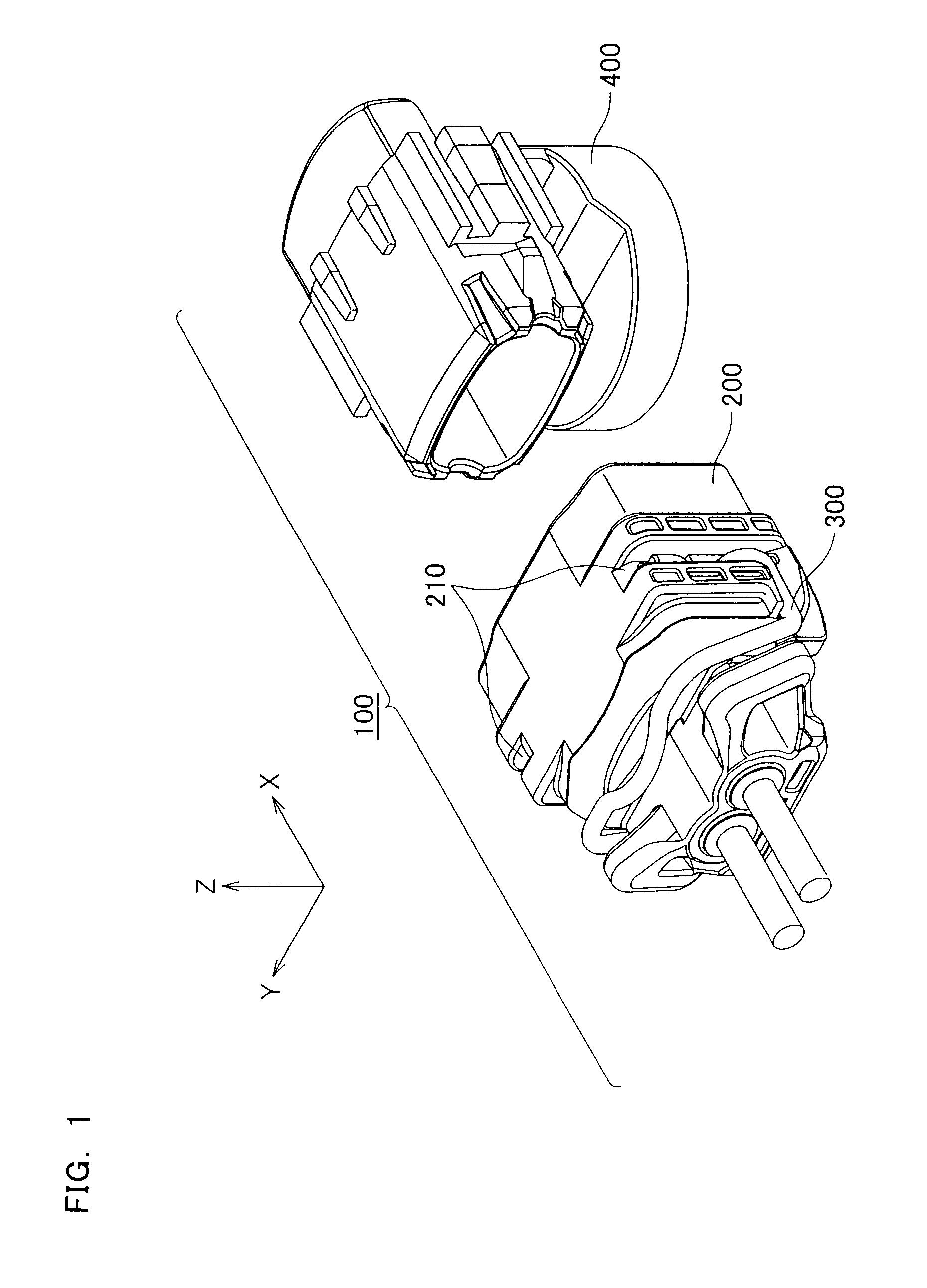
[0040]FIG. 1 is a schematic perspective view showing one example of an electrical connector 100 according to one embodiment of the present invention.

[0041]As shown in FIG. 1, the electrical connector 100 according to the present embodiment includes a female housing 200, a latch metal 300, and a male housing 400.

[0042]As shown in FIG. 1, guide ways 210 are provided in a direction parallel to a direction (a direction of an arrow Z in the drawing) perpendicular to a direction in which the housing 200 and the male housing 400 are made to mate with one another (a direction of an arrow X in the drawing) in the female housing 200. The latch metal 300 is pressed (from the direction of the arrow Z toward the direction of −Z) to fit into the guide ways 210 of the female housing 200.

[0043]A pair of first...


PUM


Abstract

The present invention provides a connector capable of being simply and easily connected without loss of electrical continuity even in a harsh environment.First joining terminals 201a and 201b are supported by a female housing 200, and second joining terminals 401a and 401b electrically connected to the first joining terminals 201a and 201b are supported by a male housing 400. The male housing 400 is inserted to mate with the female housing 200, which performs electrical connection. Further, slit ribs 205a to 205d are formed in the direction of mating in the female housing 200, and slits 405a to 405d along the direction of mating are formed in the male housing 400. The slit ribs 205a to 205d have recessed tapered shapes formed at a predetermined rate of angular change and a predetermined rate of width change, and the slits 405a to 405d have tapered shapes having a rate of angular change and a rate of width change which are respectively greater than the predetermined rate of angular change and the predetermined rate of width change of the slit ribs.

Description

TECHNICAL FIELD[0001]The present invention relates to a connector capable of performing electrical continuity even in a harsh environment.BACKGROUND ART[0002]In recent years, in a power source (for example, an engine) used for a vehicle such as an automobile, various electronic controls have been used in order to comply with restrictions regarding fuel savings or emissions control, and the like. In order to perform these electronic controls, a sensor, an actuator, a control device (for example, an electronic control unit: ECU), cables and electrical connectors for connecting equipment, and the like are mainly required.[0003]However, in the vicinity of a power source, in particular, a direct fuel-injection engine or the like, electrical connectors thereof are placed in a harsh environment. That is, because high-acceleration vibration is caused in the vicinity of such a power source, housings of an electrical connector are easily worn away or made defective, which makes it difficult t...

Claims


Application Information

Patent Timeline
Patent Type & Authority Patents(United States)
IPC IPC(8): H01R13/64
CPCH01R13/533H01R13/6277H01R13/639H01R2201/26
Inventor SHINDO, SATORUMIYAZAKI, YUJIKOBAYASHI
Owner JST MFG CO LTD
Why Eureka
Try Eureka