Heating device having hanging portion

Inactive Publication Date: 2011-08-04
CAMPBELL STEPHANIE
View PDF9 Cites 12 Cited by
  • Summary
  • Abstract
  • Description
  • Claims
  • Application Information

AI Technical Summary

Benefits of technology

[0007]What is needed is a heating device

Problems solved by technology

In either of the first two cases, the design of the warming pad is limited to a construction that is both safe and comfortable for the occupant during its use.
In the case of the temporary bed warmer which is inserted into the occupants sleeping space prior to sleep, the prior art devices have typically made use of hot air blowers and distribution tubes, rigid box shaped enclosures with resistive heating elements, or heavy gel or fluid filled containers; all of which present an in

Method used


Image

  • Heating device having hanging portion
  • Heating device having hanging portion
  • Heating device having hanging portion

Examples


Example

[0029]The present invention recognizes and addresses the disadvantages of prior art construction limitations, application limitations, mobility limitations, and storage difficulties.

[0030]Reference is made in detail to presently preferred embodiments of the invention, one or more examples of which are illustrated in the accompanying drawings. Each example is provided by way of explanation of the invention, not limitation of the invention. In fact, it will be apparent to those skilled in the art that modifications and variations can be made in the present invention without departing from the scope or spirit thereof. For instance, features illustrated or described as part of one embodiment may be used on another embodiment to yield a still further embodiment. Thus, it is intended that the present invention covers such modifications and variations as come within the scope of the appended claims and their equivalents.

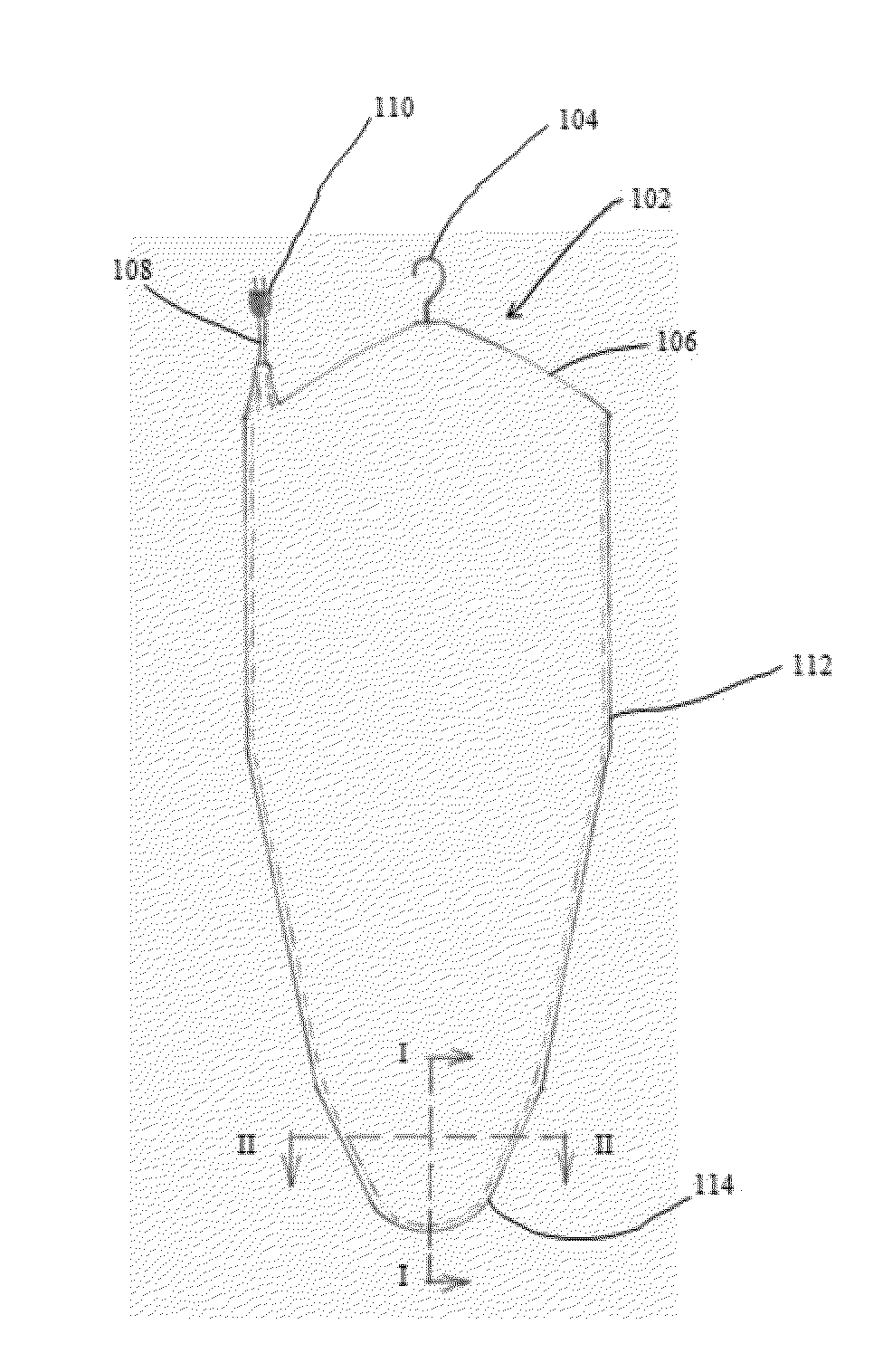
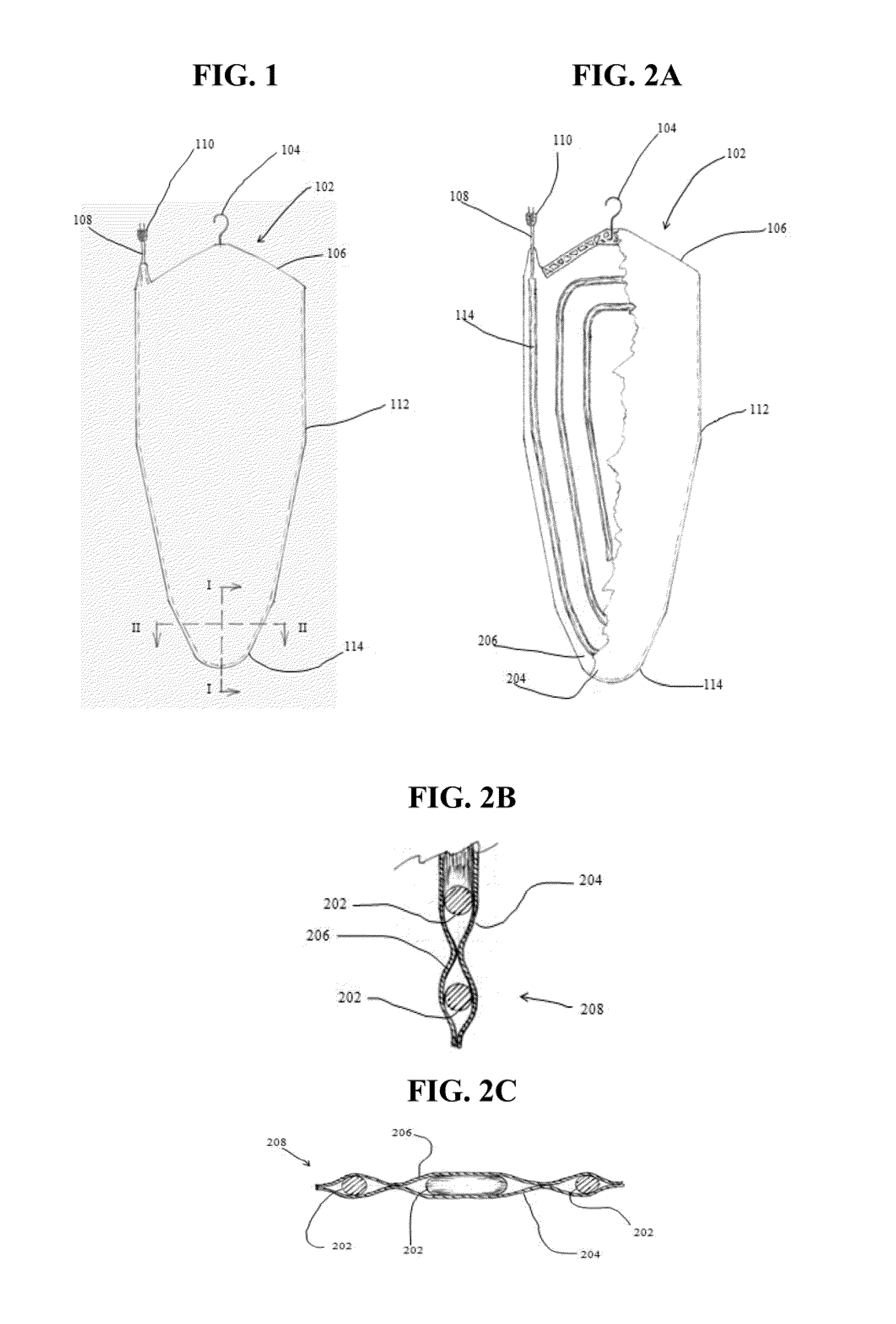
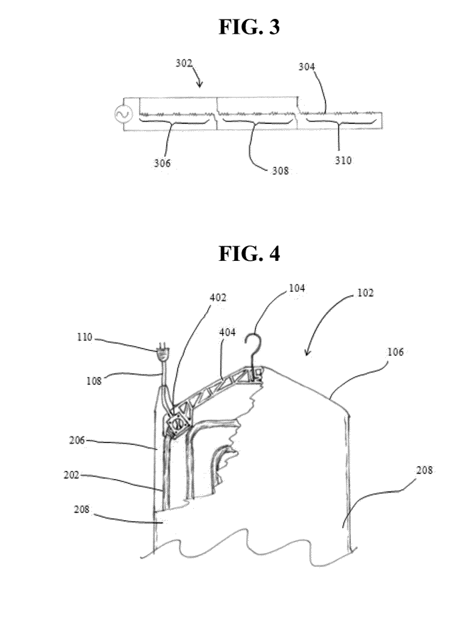
[0031]A flexible warming pad of the present invention is denoted by th...


PUM


Abstract

A device is provided that includes an enclosure, a heating element and a hanging portion. The enclosure has a first end and a top surface. The heating element is disposed within the enclosure. The hanging portion is connected to the first end and can hang the enclosure in a direction that is normal to the top surface.

Description

[0001]The present application claims priority from U.S. Provisional Application No. 61 / 337,334 filed Feb. 3, 2010, the entire disclosure of which is incorporated herein by reference.BACKGROUND[0002]The present invention relates generally to flexible electric warming pads.[0003]One form of flexible electric warming pad is used for bed warming and typically includes a heating element that extends through the warmer and through which electric current passes to generate heat. These bed warming devices are typically applied to the top of the mattress pad for semi permanent use, applied along with the sheets or blankets as a heated covering, or inserted temporarily into the sleeping space prior to the occupant's arrival into the bed. In either of the first two cases, the design of the warming pad is limited to a construction that is both safe and comfortable for the occupant during its use.[0004]Electromagnetic field effects should be considered relative to their long term effect on the h...

Claims


Application Information

Patent Timeline
IPC IPC(8): H05B1/00
CPCH05B2203/002H05B2203/014H05B3/34H05B2203/036H05B2203/016D06F59/02
Inventor CAMPBELL, STEPHANIE
Owner CAMPBELL STEPHANIE
Why Eureka
Try Eureka