Can end

a technology of can end and end, which is applied in the field of can end, can solve the problems of hindering tab access for consumers and hard for consumers to engage the tab with their fingers, and achieve the effects of reducing stiffening effect, reducing the force required to cause “pop-up”, and reducing the increase of pop-up pressur

Active Publication Date: 2011-08-04
CROWN PACKAGING TECH
View PDF100 Cites 13 Cited by
  • Summary
  • Abstract
  • Description
  • Claims
  • Application Information

AI Technical Summary

Benefits of technology

[0011]Can ends of type (ii) are often used for beverage applications for which a smaller aperture is desirable to enable the product to be drunk or poured straight from the can. The smaller aperture size makes it practical for the openable panel portion to be retained by the can end; e.g. by being folded inwards into the container body. The retaining of the openable panel portion reduces litter.
[0013]Conveniently, the moveable portion is formed as an integral part of the can end. It has been found beneficial to use a press to form the moveable portion in the material of the can end. In simple terms, the moveable portion results in a can end which is bi-stable. By “bi-stable”, it is meant that the moveable portion can adopt one of two different states: the “up” (convex) position, and the “down” (concave) position. However, it has been found that incorporating the downwardly inclined annular step of the present invention provides additional stiffening to the moveable portion. The stiffening effect is such that it increases the force required for the moveable portion to “pop-up” from the down position to the up position, relative to the same can end without the annular step. As the stiffening effect due to the annular step increases, the moveable portion behaves more like a mono-stable end in that once the moveable portion has been deformed into its “down” (concave) position, it is highly resistive to being deformed back into an “up” (convex) position. Further, this increase in stiffening is achieved without increasing the thickness of the metal used to form the can end. Increasing the metal thickness would result in increased material costs. In summary, when used on a container body, the present invention results in a container better able to withstand impacts and / or transportation at high altitudes (where the atmospheric pressure is reduced), without the moveable portion of the can end reverting or popping back into the “up” (convex) position. Therefore, there is a greater likelihood of a consumer receiving a container / can end providing adequate tab access for a consumer's finger. Whilst the can end may remain bi-stable, the annular step results in a higher force being required to deform the moveable portion back into the “up” (convex) position, i.e. an increase in the “pop-up” force.
[0017]The can end of the present invention may be manufactured with the moveable portion initially in either the “up” position or the “down” position. Where the can ends are transported between locations for later attachment to a can body, it is preferred that the moveable portion is deformed into the “up” position because this allows for easy stackability of the can ends.
[0020]The table illustrates that the inclusion of a single downwardly inclined annular step (Design ‘B’) greatly increased the pressure differential required to cause the protrusion to “pop-up” relative to Design ‘A’. It also had the effect of increasing the pressure differential required to cause “pop-down” relative to Design ‘A’. In these particular tests, the annular step resulted in a 126% increase in the pressure required to cause pop-up of the protrusion.
[0025]It is an essential requirement for the downwardly inclined annular step to be located on or to extend onto the moveable portion itself. In order to maximise the force required to cause “pop-up”, it has been found preferable for the annular step to be located near the periphery of the moveable portion. Conveniently, the annular step is formed at a location on or between the periphery of the moveable portion and a distance of up to 50% radially inwardly of the periphery of the moveable portion. Locating the annular step close to the centre of the moveable portion would have the disadvantage of reducing the stiffening effect provided by the annular step and would result in a lower increase in pop-up pressure.
[0026]The annular step is preferably circular in plan because this shape maximises the force required to cause the moveable portion to pop back up into the “up” (convex) position. In other words, it has been found to provide the optimum stiffening effect. However, other profiles for the annular step (e.g. elliptical or irregular in plan) may also be used.

Problems solved by technology

A tab is provided on the can end, with lifting of the tab by a consumer initiating fracture of the score line and subsequent pulling on the tab resulting in opening of the can end about the opening area.
Historically, the opening of such easy open ends was made difficult by limited clearance between the tab and the can end, thereby making it hard for a consumer to engage the tab with their fingers.
However, it has been found that during subsequent handling of containers incorporating can ends of the type described in WO 03 / 104092 A (i.e. after filling and any retort processing), there can be a tendency for the protrusion to “pop up” back into its upward position, thereby hindering tab access for a consumer.
The cause of the popping-up could be, for example, impacting of the container against other containers or being dropped onto the floor.

Method used


Image

  • Can end
  • Can end
  • Can end

Examples


Embodiment Construction

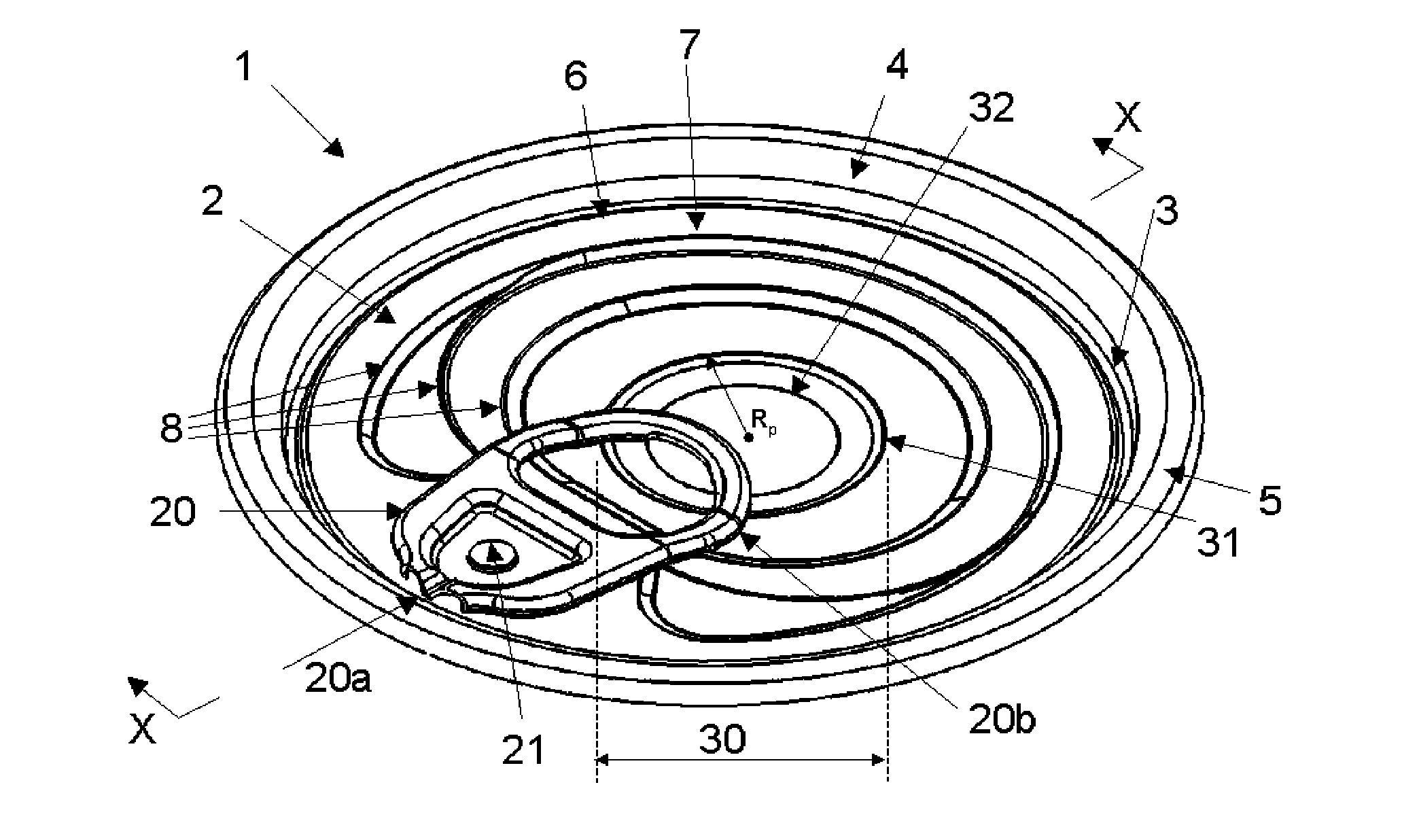
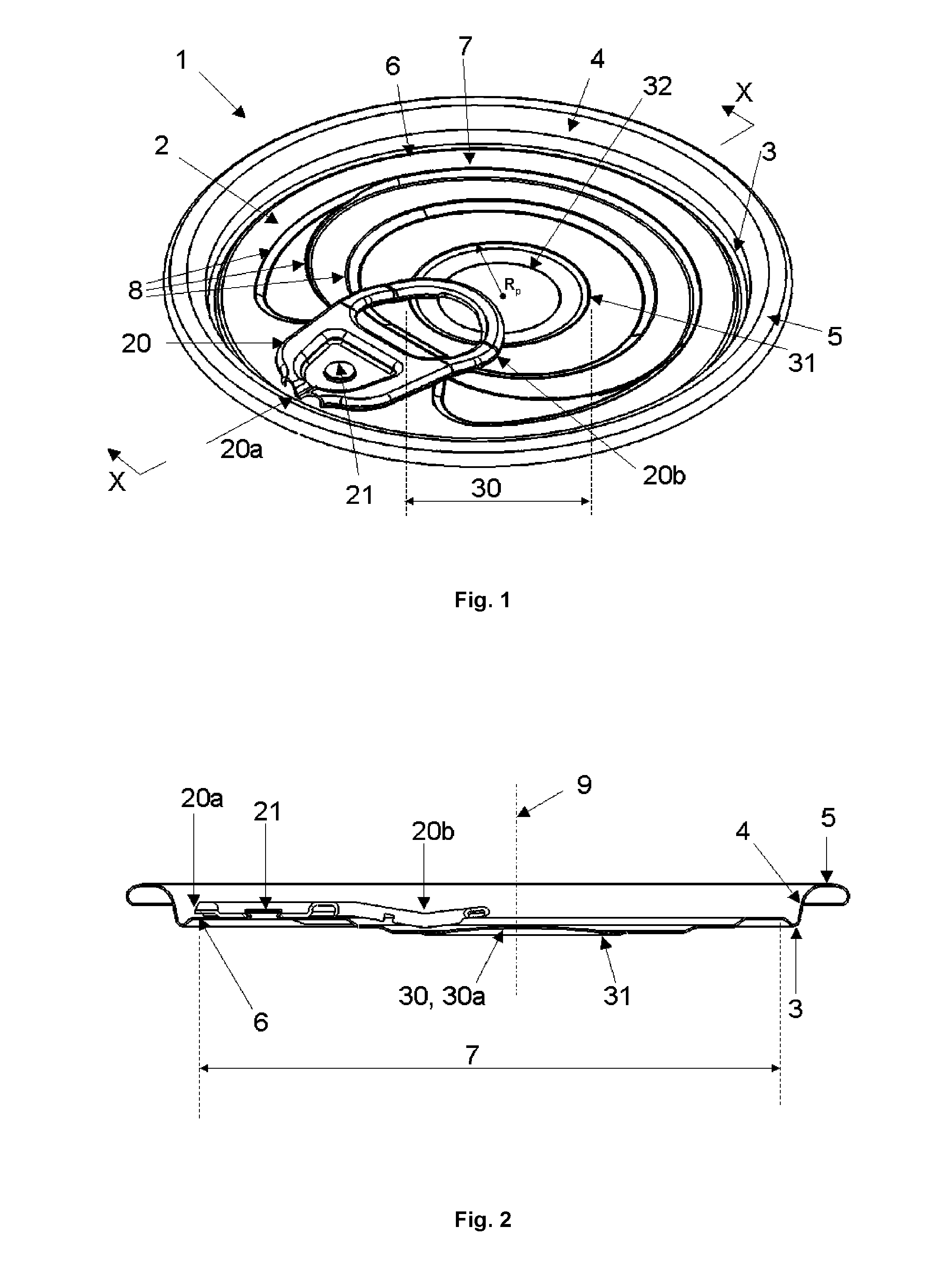
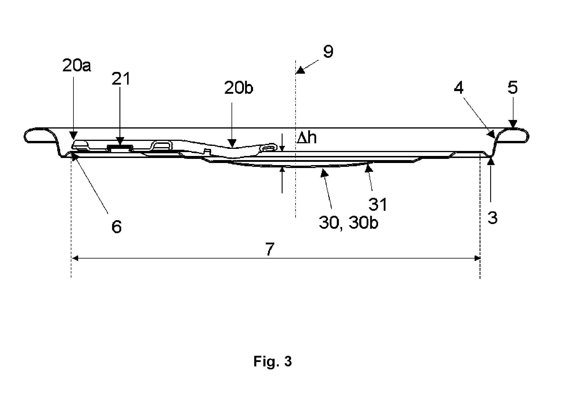
[0043]FIG. 1 shows can end 1. In the embodiment shown, the can end 1 is formed of 0.21 mm gauge DR550N material. The can end 1 has a central panel 2 with a countersink 3 at its periphery. The countersink 3 extends upwardly into a chuck wall 4, with the chuck wall extending radially outwards to form a seaming panel 5. A circular score line 6 is formed in the can end 1, defining an openable panel portion 7 inwards of the score line. The score line 6 (once severed) defines an aperture through which product (not shown) is dispensed, with the openable panel portion 7 being completely detachable from the can end 1. Beading 8 is provided on the central panel 2 for the purpose of strengthening the central panel 2.

[0044]A tab 20 is attached to the central panel 2 by means of a rivet 21. One end of the tab 20 is provided with a nose portion 20a situated adjacent to the score line 6. The opposite end of the tab 20 is provided with a handle portion 20b in the form of a ring.

[0045]A moveable por...


PUM


Abstract

This invention relates to a can end (1) providing improved tab access for a consumer. A further aspect of the present invention relates to a container incorporating such a can end (1). The can end (1) includes a moveable portion (30) located beneath all or part of the handle (20b) of the can end, with the moveable portion deformable from an ‘up’ position (30a) to a ‘down’ position (30b) to provide increased tab access for a consumer. The can end (1) is provided with one or more downwardly inclined annular steps (31), which has been found to greatly increase the force required to deform the panel from the ‘down’ to the ‘up’ position, therefore resulting in a far greater likelihood of the consumer receiving a container (40) incorporating the can end (1) with the moveable portion (30) in the ‘down’ position (30b), thereby facilitating tab access.

Description

TECHNICAL FIELD[0001]This invention relates to a can end providing improved tab access for a consumer. A further aspect of the present invention relates to a container incorporating such a can end.BACKGROUND ART[0002]In the field of metal packaging, easy open ends for metal cans are well known. Typically, an easy open can end takes the form of a metal panel including a score line defining an opening area on the can end. A tab is provided on the can end, with lifting of the tab by a consumer initiating fracture of the score line and subsequent pulling on the tab resulting in opening of the can end about the opening area. Historically, the opening of such easy open ends was made difficult by limited clearance between the tab and the can end, thereby making it hard for a consumer to engage the tab with their fingers. WO 03 / 104092 A (MAEIL DAIRY INDUSTRY CO., LTD) 18.12.2003 (subsequently assigned to CROWN Packaging Technology, Inc for US and EP designations) provided a solution to this...

Claims


Application Information

Patent Timeline
Patent Type & Authority Applications(United States)
IPC IPC(8): B65D17/34
CPCB65D17/163B65D2517/0079B65D2517/0016B65D17/165B65D17/4011B65D17/4012
Inventor DUNWOODY, PAUL ROBERTPAILLET, LAURE HELENE MARIE
Owner CROWN PACKAGING TECH
Why Eureka
Try Eureka