Gas turbine and method for varying the aerodynamic shape of a gas turbine blade
- Summary
- Abstract
- Description
- Claims
- Application Information
AI Technical Summary
Benefits of technology
Problems solved by technology
Method used
Image
Examples
Example
DETAILED DESCRIPTION OF THE DRAWINGS
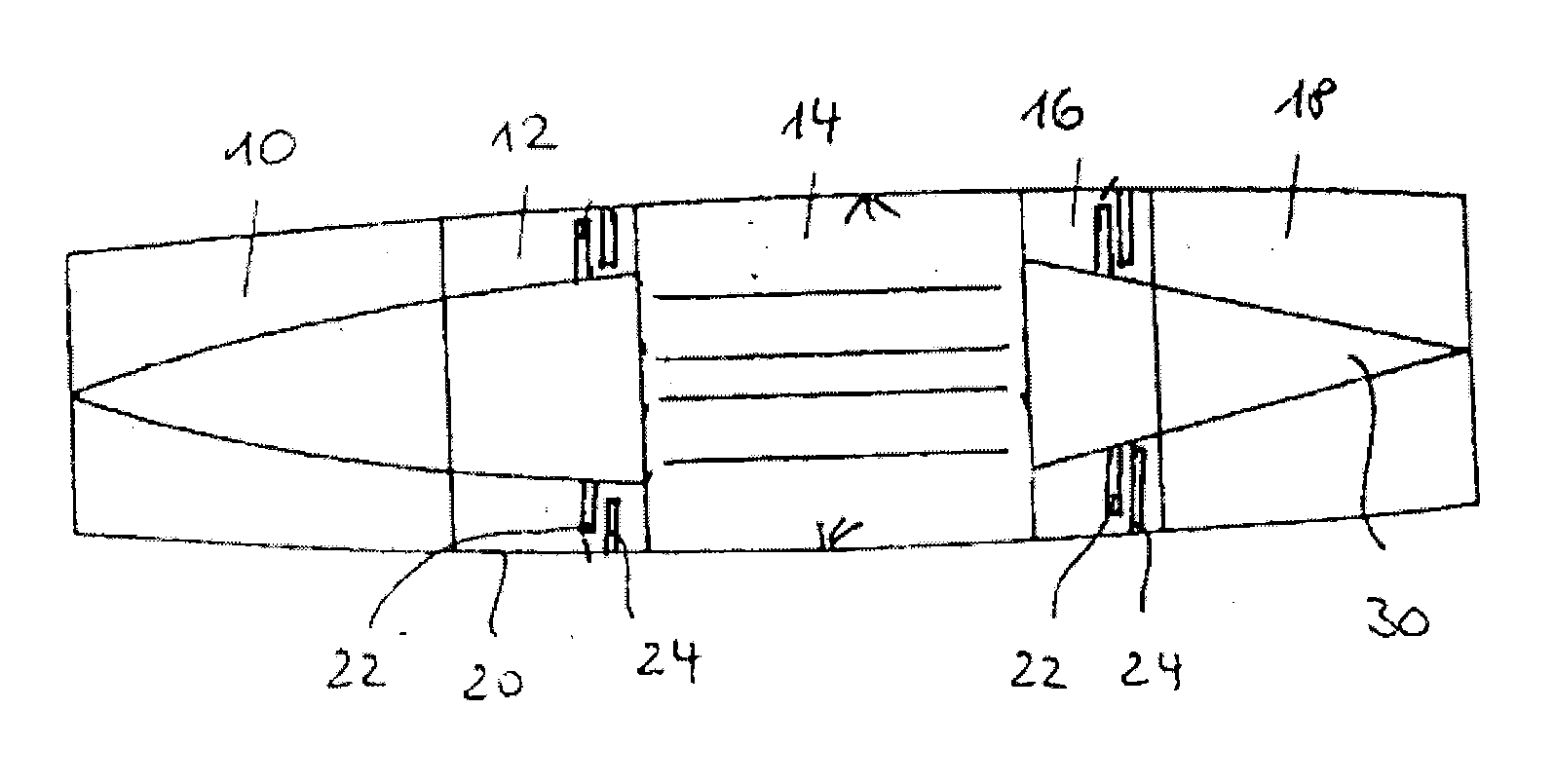
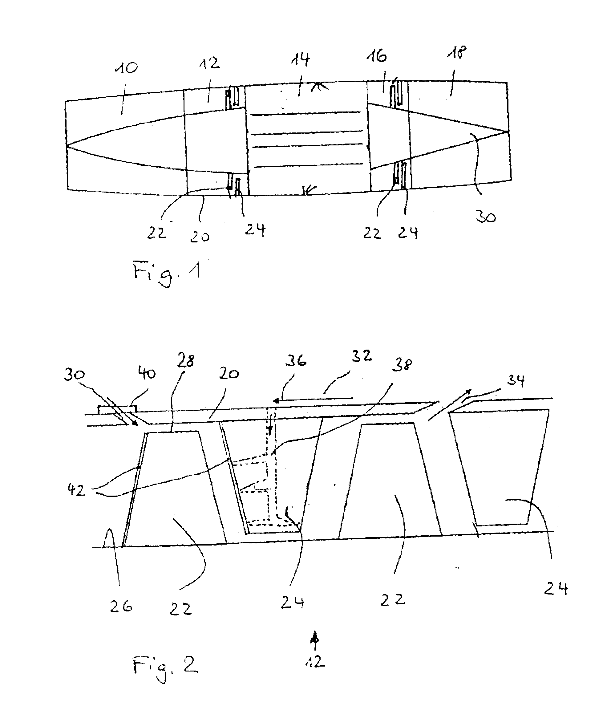
[0023]FIG. 1 depicts a gas turbine having an inlet diffuser 10, a compressor 12, a combustion chamber 14, a turbine 16 and a thrust nozzle 18, all of which are situated in a housing 20. Only by way of example, several of the numerous rotor blades 22 are depicted as part of the rotor and guide blades 24 are depicted as part of the stator in the compressor section or turbine section.
[0024]FIG. 2 shows that the depicted compressor 12 is multi-stage and has an axial design. It is easy to see that the guide blades 24 are connected to the housing 20 and the rotor blades 22 are connected to the rotor 26.
[0025]Directly upstream from the so-called blade tip 28 of a rotor blade ring, the housing 20 has several uniformly distributed blow-in openings 30 for hot gas on the circumference. The blow-in openings 30 are the end of one or more channels 32, which direct hot air upstream from a downstream compressor stage via one or more outlet openings 34. Arrow 36 s...
PUM
| Property | Measurement | Unit |
|---|---|---|
| Shape | aaaaa | aaaaa |
Abstract
Description
Claims
Application Information
 - R&D
- Intellectual Property
- Life Sciences
- Materials
- Tech Scout
- Unparalleled Data Quality
- Higher Quality Content
- 60% Fewer Hallucinations
Browse by: Latest US Patents, China's latest patents, Technical Efficacy Thesaurus, Application Domain, Technology Topic, Popular Technical Reports.
© 2025 PatSnap. All rights reserved.Legal|Privacy policy|Modern Slavery Act Transparency Statement|Sitemap|About US| Contact US: help@patsnap.com


