

Thin refrigeration air conditioner having a greater temperature difference
- Summary
- Abstract
- Description
- Claims
- Application Information
AI Technical Summary
Benefits of technology
Problems solved by technology
Method used
Image

Examples
first embodiment
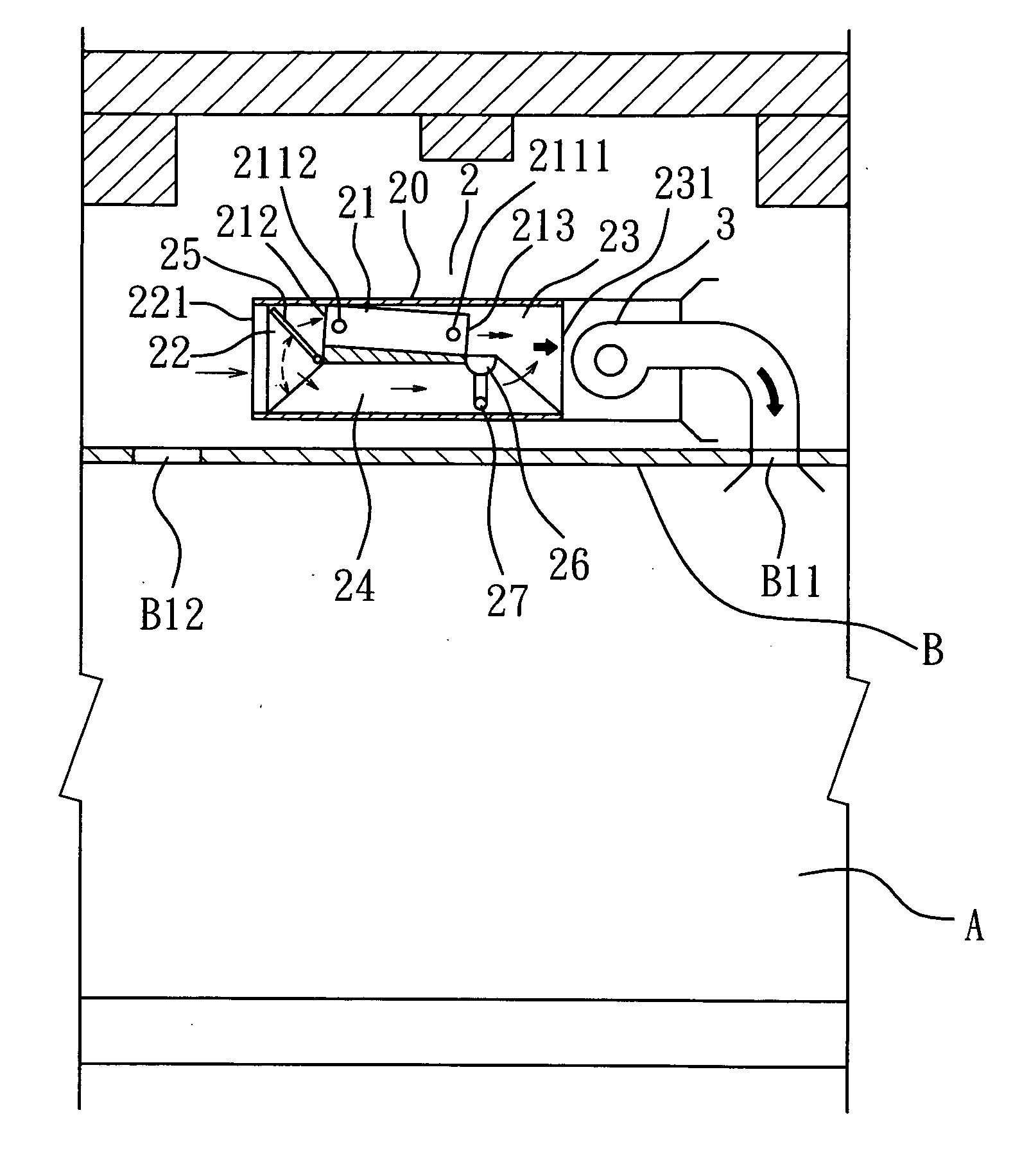
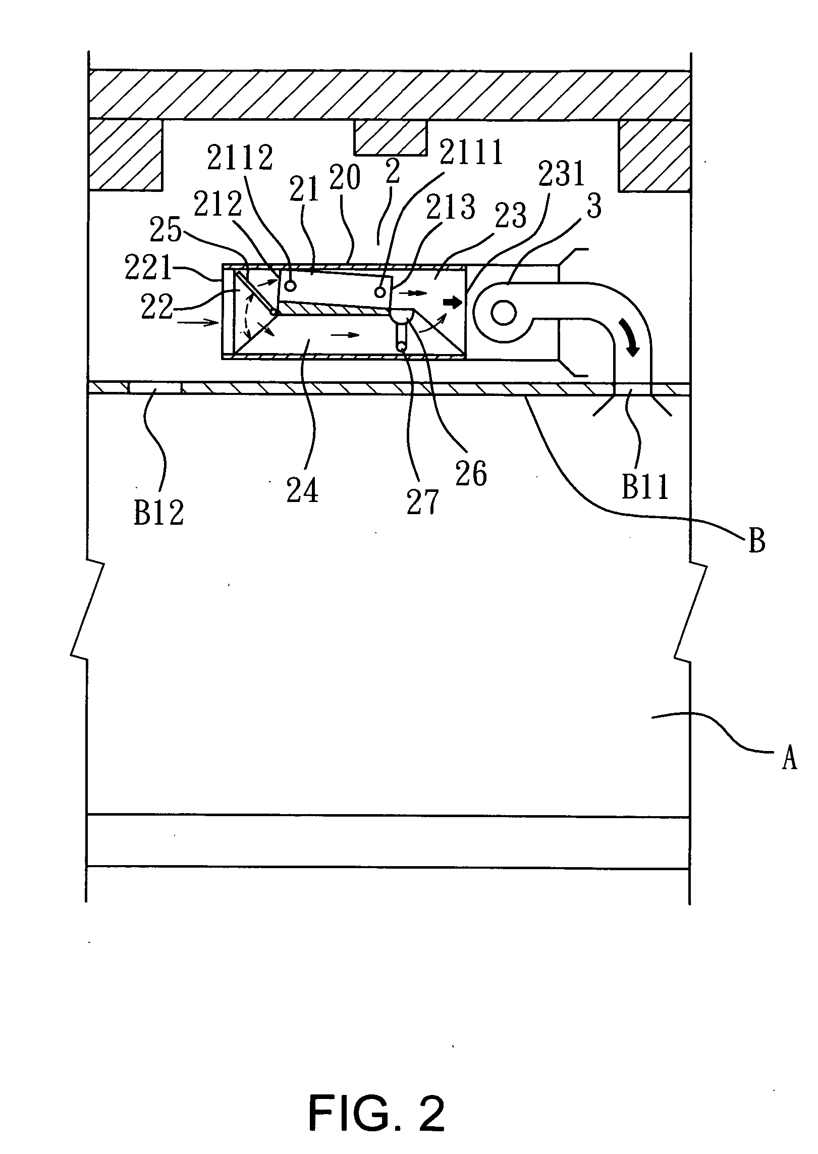
[0018] Referring to FIGS. 2 and 3 for the invention. The thin refrigeration air conditioner 2 has an air fan motor 3 on one side (a front side or rear side). Air passes through the thin refrigeration air conditioner 2 to perform heat exchange, then is discharged through one or more air outlet B11 located on a ceiling B into an A / C room A to meet A / C requirement. The thin refrigeration air conditioner 2 includes a casing 20 which houses a thin heat exchanger 21, an air intake chamber 22, an air exit chamber 23, a side chamber 24 and an air port baffle 25.
[0019] The thin heat exchanger 21 contains a piping assembly 211 which has a refrigerant input end 2111 and a refrigerant output end 2112. The piping height H of the thin heat exchanger 21 is much smaller than the longitudinal length D of the piping, thus is a thin structure (referring to FIGS. 2 and 4). It further has a water collection tray 26 and a water discharge tube 27 on a rear end of the bottom thereof.
[0020] The air intake ...
third embodiment
[0028] Refer to FIG. 6 for the invention. The refrigeration air conditioner 5 has an air fan motor 3 on one side. The refrigeration air conditioner 5 includes a casing 50 which houses a thin heat exchanger 51, an air intake chamber 52, an air exit chamber 53, a side chamber 54 and an air port baffle 55. The side chamber 54 further has a return air branch port 56 on the bottom. And the air intake chamber 52 and the side chamber 54 are divided by a spacer 57 without communicating with each other. The air port baffle 55 is located in the side chamber 54 and controlled by the controller 8 (referring to FIG. 9). The air port baffle 45 opens at a desired degree to control the amount of the second time air flowing through the return air branch port 56. After the second time air has entered the air exit chamber 53 and mixed up with the first time air, the temperature difference between the delivered A / C air and the return air from the return air branch port 56 is maintained at a minimum ran...
fourth embodiment
[0029] Refer to FIG. 7 for the invention. The refrigeration air conditioner 6 has an air fan motor 3 on one side. The refrigeration air conditioner 6 includes a casing 60 which houses a thin heat exchanger 61, an air intake chamber 62, an air exit chamber 63, a side chamber 64 and an air port baffle 65. The side chamber 64 further has a return air branch port 66 on the bottom. And the air intake chamber 62 and the side chamber 64 are divided by a spacer 67 without communicating with each other. The air port baffle 65 is located in the air exit chamber 63 and controlled by the controller 8 (referring to FIG. 9). The air port baffle 65 opens at a desired degree to control the amount of the first time air flowing out from the thin heat exchanger 61 and the second time air entering the side chamber 64.
PUM
 Abstract
Description
Claims
Application Information