High-Temperature Heat Exchanger

Active Publication Date: 2014-09-18
WS WARMEPROZESSTECHN
View PDF13 Cites 9 Cited by
  • Summary
  • Abstract
  • Description
  • Claims
  • Application Information

AI Technical Summary

Benefits of technology

The invention is a heat exchanger that meets certain conditions to achieve high efficiency, compact design, and low production costs. It has a large temperature difference, high transfer efficiency, high packaging density, and long service life with low pressure drops. The tube bundle has an expansion designed to achieve a uniform gas distribution, which allows for a good prerequisite for arranging the flat tubes in a compact way. The flat tubes have a specific gap width and arrangement density. The invention provides a solution that saves production effort by having all flat tubes with the same shape.

Problems solved by technology

Corresponding heat exchangers must satisfy different requirements, which can only be combined with difficulty to some extent.

Method used


Image

  • High-Temperature Heat Exchanger
  • High-Temperature Heat Exchanger
  • High-Temperature Heat Exchanger

Examples


Embodiment Construction

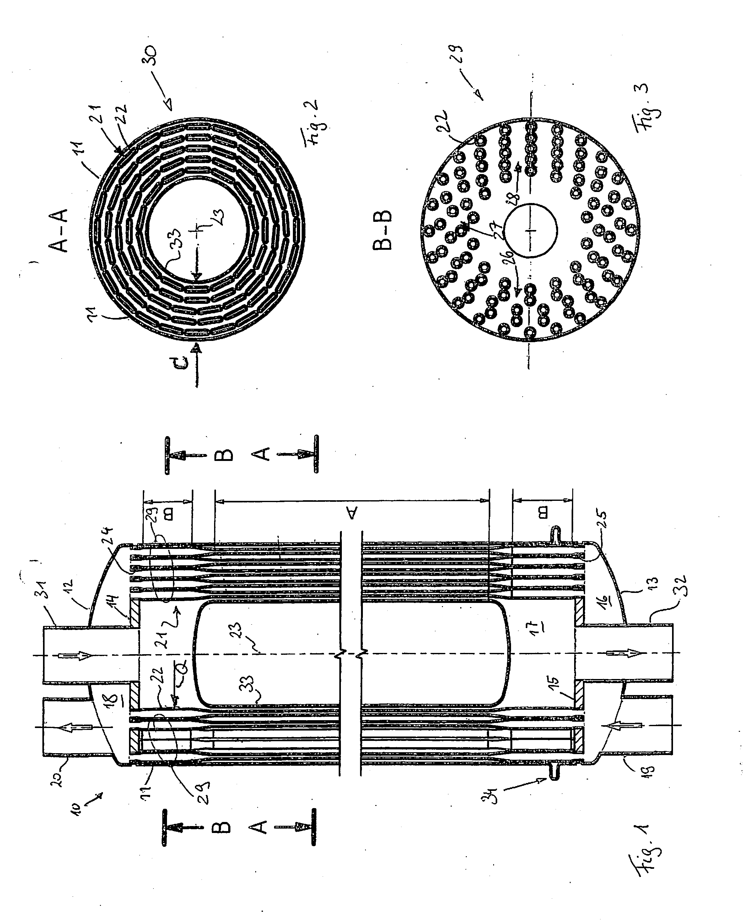
[0042]FIG. 1 illustrates a flat tube heat exchanger 10, which is accommodated here in a cylindrical housing 11. Preferably, curved cover lids 12, 13, which belong to the housing 11 and which can be a part thereof, e.g., are attached at both ends of the housing 11. The housing 11, together with the lids 12, 13, encloses an inner space, which is divided into a total of three spaces, namely a collecting space 16 (FIG. 1, bottom) at the inlet side, a tube bundle space 17 and a collecting space 18 at the outlet side, by means of two tube sheets 14, 15. The collecting spaces 16, 18 are in each case provided with a connection 19, 20. Cold air, e.g., is applied to the connection 19. Hot air, e.g., is to be emitted at the connection 20.

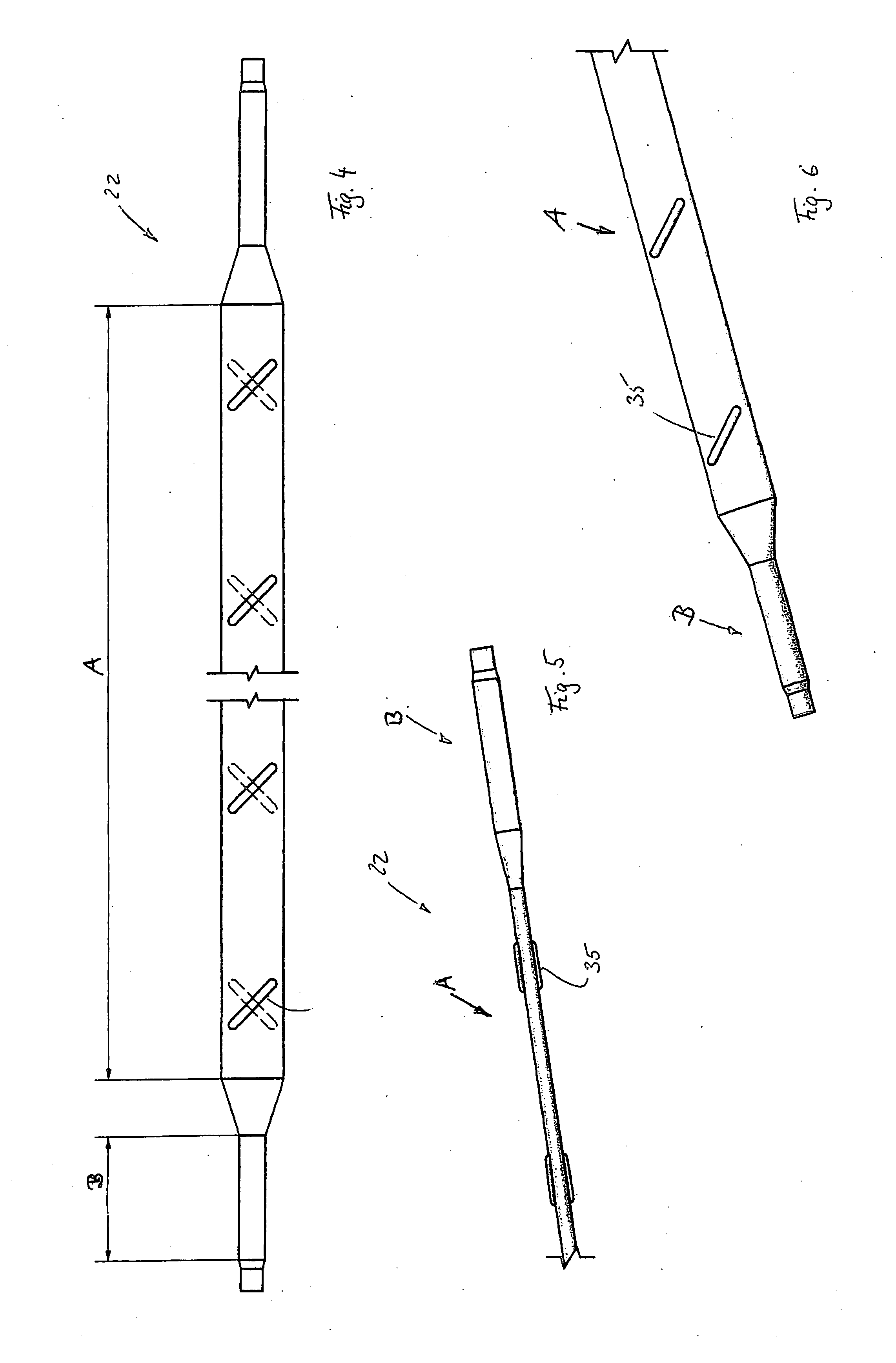
[0043]A tube bundle 21 is arranged between the tube sheets 14, 15. Said tube bundle 21 consists of numerous flat tubes 22, which are preferably embodied equally among one another. The transverse sections of the flat tubes 22 encompass straight shoulders, which...


PUM


Abstract

This flat tube heat exchanger encompasses a closed housing, in which two tube sheets and a tube bundle, which is arranged between the tube sheets and which is supported by the tube sheets is arranged. The tube bundle comprises at least some flat tubes, which extend in longitudinal direction of the tube bundle. At their ends, the flat tubes are round and are flat in a central section. The ends of the flat tubes, which have a round cross section, can be circular or can encompass a different round shape.

Description

CROSS REFERENCE TO RELATED APPLICATION[0001]The present application is based upon and claims the benefit of PCT / EP2012 / 069873, filed 8 Oct. 2012; which is based on European patent application no. 11 185 815.5, filed 19 Oct. 2011.BACKGROUND OF THE INVENTION[0002]The invention relates to a high-temperature heat exchanger, in particular for gaseous media.[0003]The energy efficiency of high-temperature processes can be increased considerably with the help of gas / gas heat exchangers, if the heat exchangers transfer the heat content of a gas flow to another gas flow as completely as possible. The gas flows can be reactants and products, for example, of a chemical reaction process, for example in the form of a combustion process. The reaction can take place in a SOFC combustion cell or a fuel cell system, for example, in micro gas turbines or other thermal engines. In many cases, the mass or heat capacity flows, respectively, of the two gases (e.g. fresh air and exhaust gas) are thereby ap...

Claims


Application Information

Patent Timeline
IPC IPC(8): F28D7/16
CPCF28D7/1615F28D7/1661F28D7/1676F28D7/1692F28F1/006F28F2265/26F28D7/16F28F13/08F28F9/0243F28F2009/224F28F2009/226
Inventor WUNNING, JOACHIM A.
Owner WS WARMEPROZESSTECHN
Why Eureka
Try Eureka